All the corresponding value of pulse output
Frequency are positive.
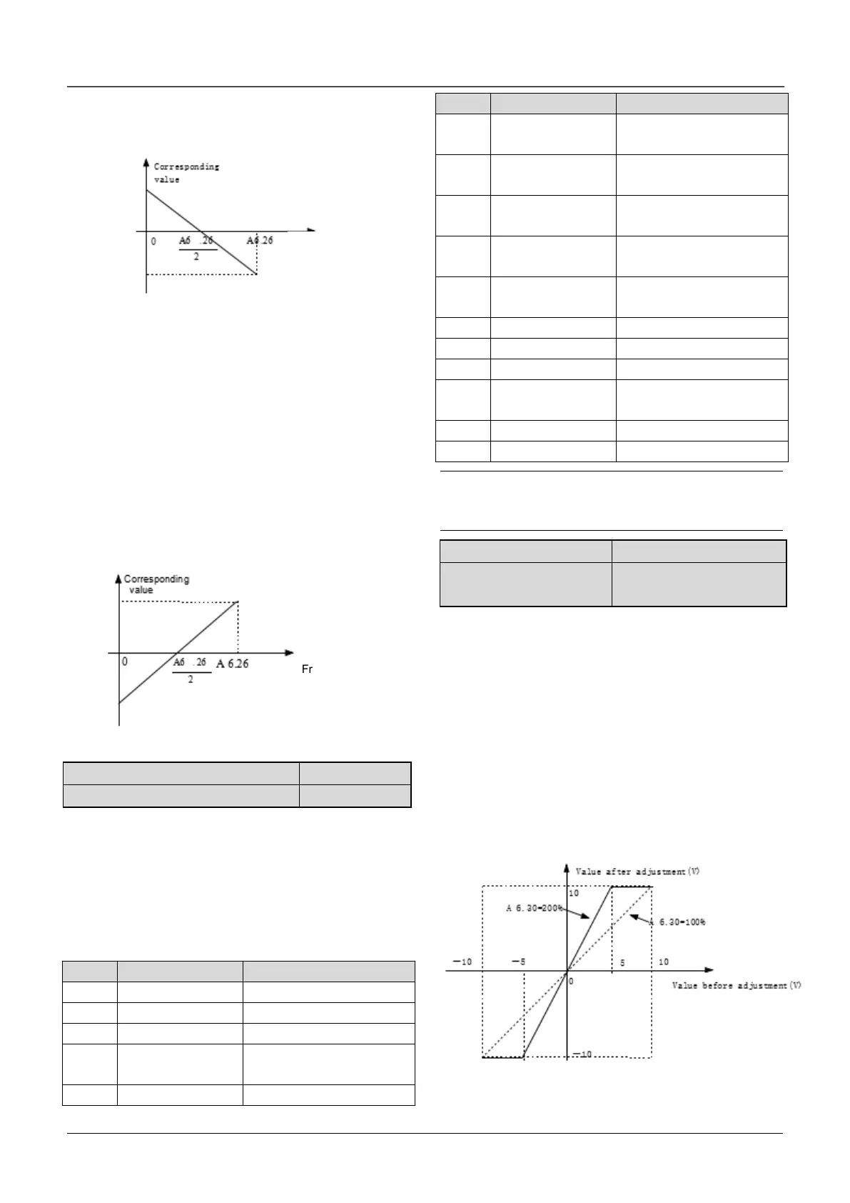
1:Center point mode 1.Shown as following figure.
Fig.6-29 Center point mode 1
There is a center point in pulse output. The value of
the cent point is a half of max. output pulse
frequency (A6.28).The corresponding value is
positive when the output pulse frequency is less
than center point.
2: Center point mode 2
There is a center point in pulse output. The value of
the center point is a half of max. output pulse
frequency (A6.28).The corresponding value is
positive when the input pulse frequency is greater
than center point.
Fig.6-30 Center point mode 2
A6.30 Functions of terminal AO1
A6.31 Functions of terminal AO2
Refer to section 4.2 for the output characteristics of
AO1 and AO2.
The relationship between the displaying range and
the output values of AO1 and AO2 is shown as
Table 6-8
Table 6-8 Displaying range of Analog output
Preset frequency
(After Acc/Dec)
0~2 times of drive’s
rated current
0~2 times of motor’s
rated current
0~3 times of motor’s
rated torque
0~3 times of motor’s
rated torque
0~1.2 times of drive’s
rated voltage
Note:
The external resistor is advised to be lower than
400Ω when AO output current signal.
A6.33 Zero offset
calibration of AO1
For the analog output AO1 and AO2, adjust the gain
if user need to change the display range or calibrate
the gauge outfit error. 100% of zero offset of analog
output is corresponding to the maximum output
(10V or 20mA).Take output voltage for example, the
relationship between the value before adjustment
and with after adjustment is as following:
AO output value = (Gain of AO)×(value before
adjustment)+(Zero offset calibration)×10V
The relationship curve between analog output and
gain and between analog output and zero offset
calibration are as Fig.6-31 and Fig.6-32.
Fig.6-31 Relationship curve between analog
output and gain
 Loading...

