Example 1 : The output voltage in V/F mode is
controlled by AI.
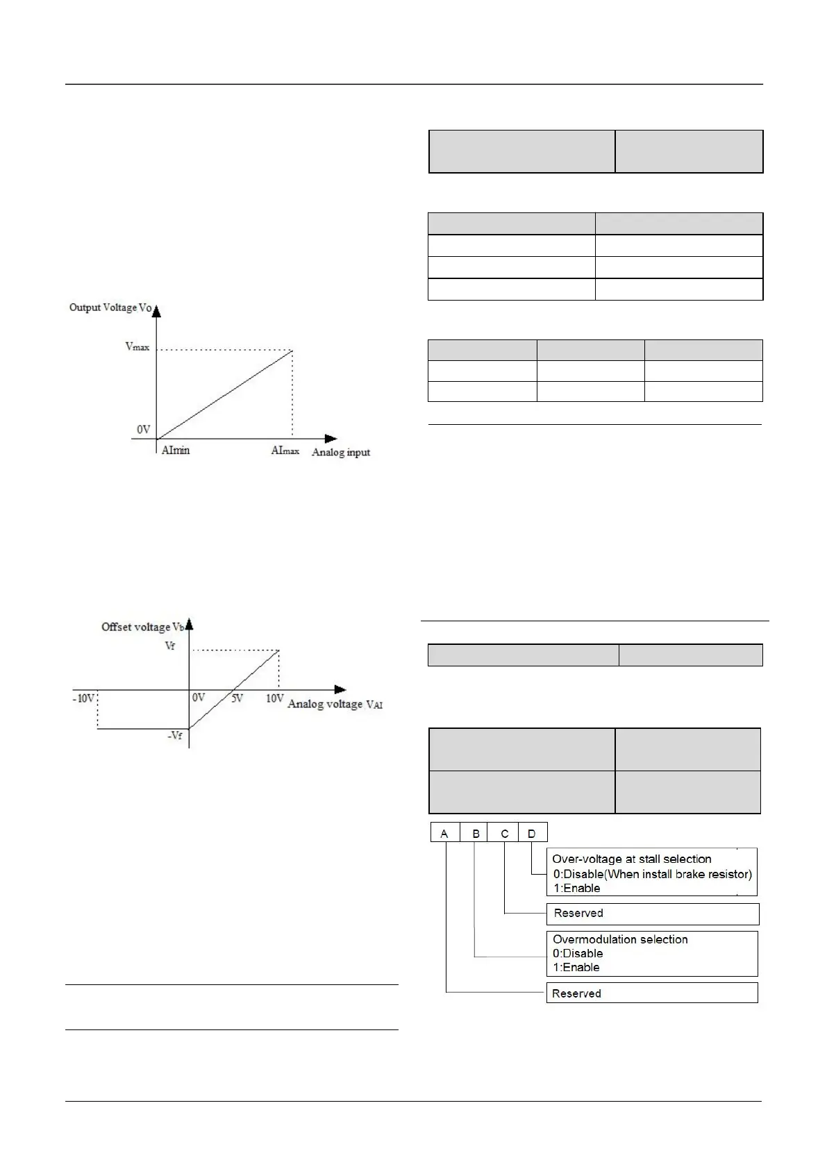
Set a value (not zero) to b1.09 to select an analog
input to control voltage output. This function is only
valid in V/F control mode. The output frequency and
output voltage VO is completely independent of
each other. The output voltage is controlled by
analog input signal, not by the V/F curve in Group
b1,as shown in Fig.6-37.
Fig.6-37 Curve of Output voltage
Example 2 : The offset of output voltage in V/F
mode is controlled by AI.
Set a value (not zero) to b1.10 to select an analog
input to control the offset of voltage output. As
shown in Fig.6-38.
Fig.6-38 Offset of output voltage
The output voltage corresponding to the setting
frequency in the V/F curve is V/F, then the
relationship between analog input and offset
voltage is as follows:
If analog input VAI is -10V~0V or 4mA, then the
corresponding offset voltage is –V or F. If analog
input VAI is 10V or 20mA, then the corresponding
offset voltage is V or F.
The output voltage is VO=V/F+Vb
Note
AI offset is only valid in V/F control mode.
Note:
1. The carrier wave frequency will affect the noise
when motor running, generally the carrier wave
frequency is supposed to set as 3~5kHz. For some
special situation where require operating mutely,
the carrier wave frequency is supposed to set as
6~8kHz.
2.When set the carrier wave frequency larger than
default value, then the power of drive need to
derate 5% by every increase of 1kHz.
During deceleration, the motor’s decelerate rate
may be lower than that of drive’s output frequency
due to the load inertia. At this time, the motor will

 Loading...
