feed the energy back to the drive, resulting in the
voltage rise on the drive's DC bus. If no measures
taken, the drive will trip due to over voltage.
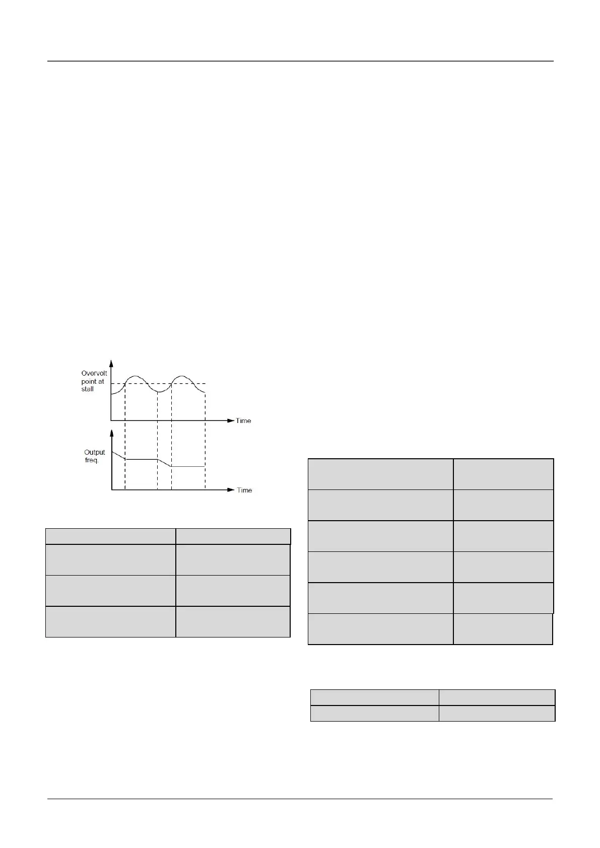
During the deceleration, the drive detects the bus
voltage and compares it with the over voltage point
at stall defined by b2.03. If the bus voltage exceeds
the stall overvoltage point, the drive will stop
reducing its output frequency. When the bus voltage
becomes lower than the point, the deceleration
continues. As shown in Fig.6-39.
The hundred’s place is used to set over modulation
function of V/F control. For vector control, the over
modulation function will be always enable. Over
modulation means when the voltage of power grid is
low for long term (Lower than 15% of rated voltage),
or is overload working for long term, then the drives
will increase the use ratio of its own bus voltage to
increase output voltage.
Fig.6-39 Over-voltage at stall
b2.05 Auto current limiting
threshold
b2.06 Frequency decrease
rate when current limiting
b2.07 Auto current limiting
selection
Droop control is used to distribute the load
automatically by adjusting the output frequency
when several VFDs drive the same load.
Auto current limiting function is used to limit the load
current smaller than the value defined by b2.05 in
real time. Therefore the drive will not trip due to
surge over-current. This function is especially useful
for the applications with big load inertia or big
change of load.
b2.05 defines the threshold of auto current limiting.
It is a percentage of the drive’s rated current.
b2.06 defines the decrease rate of output frequency
when the drive is in auto current limiting status.
If b2.06 is set too small, overload fault may occur. If
it is set too big, the frequency will change too
sharply and therefore, the drive may be in
generating status for long time, which may result in
overvoltage protection.
Auto current limiting function is always active in Acc
or Dec process. Whether the function is active in
constant speed operating process is decided by
b2.07.
b2.07=0, Auto current limiting function is disabled
in constant speed operating process;
b2.07= 1, Auto current limiting function is enabled
in constant speed operating process;
In auto current limiting process, the drive’s output
frequency may change; therefore, it is
recommended not to enable the function when the
drive’s output frequency is required stable.
When the auto current limiting function is enabled, if
b2.05 is set too low, the output overload capacity
will be impaired.
b2.08 Gain of slip
compensation
b2.09 Limit of slip
compensation
b2.10 Slip compensation time
constant
b2.11 Energy-saving function
b2.12 Frequency decrease rate
at voltage compensation
b2.13Threshold of
zero-frequency operation
This parameter is used together with No.9 function
of digital output terminal.
0: Auto operating mode.
The fan runs all the time when the drive is
operating.

 Loading...
