These parameters are used to set the motor’s
parameters. In order to ensure the control
performance, please set b0.00~b0.05 with
reference to the values on the motor’s nameplate.
Note:
The motor’s power should match that of the drive.
Generally the motor’s power is allowed to be lower
than that of the drive by 20% or bigger by 10%,
otherwise the control performance cannot be
ensured.
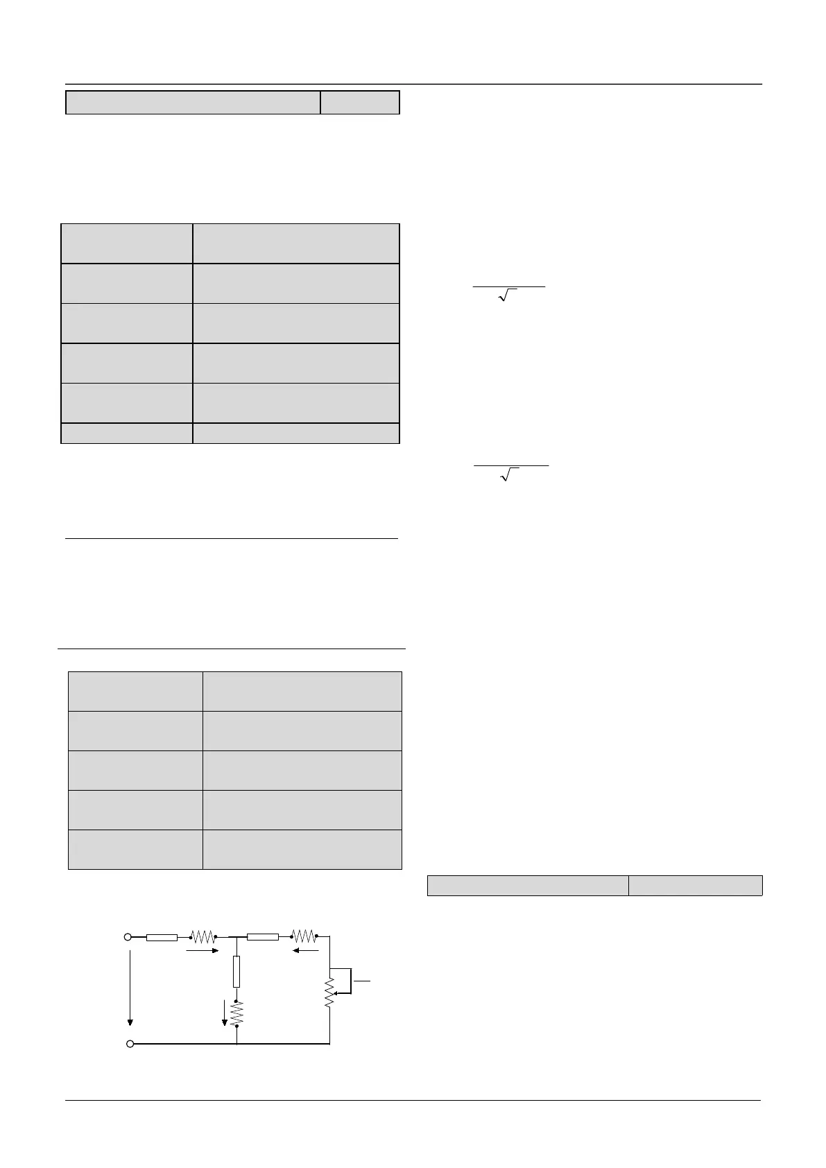
In Fig. 6-33, R1, X1l, R2, X2l, Xm and I0 represent
stator’s resistance, stator’s leakage inductance,
rotor’s resistance, rotor’s leakage inductance,
exciting inductance and current without load
respectively. The setting of b0.07 is the sum of
stator’s leakage inductance and rotor’s inductance.
The settings of b0.06 ~b0.09 are all percentage
values calculated by the formula below:
(1)
R: Stator’s resistance or rotor’s resistance that is
converted to the rotor’s side;
V: Rated voltage;
I: Motor’s rated current
Formula used for calculating inductance (leakage
inductance or exciting inductance):
(2)
X: sum of rotor’s leakage inductance and stator’s
leakage inductance (converted to stator’s side) or
the exciting inductance based on base frequency.
V: Rated voltage;
I: Motor’s rated current
If motor’s parameters are available, please set
b0.06~b0.09 to the values calculated according to
the above formula. b0.10 is the motor current
without load, the user can set this parameter
directly.
If the drive performs auto-tuning of motor’s
parameters, the results will be written to
b0.06~b0.10 automatically. After motor power
(b0.00) is changed, the drive will change
b0.02~b0.10 accordingly(b0.01 is the rated voltage
of motor, user need to set this parameter by manual
according to the value on the motor’s nameplate.)
0: Auto-tuning is disabled
1 : Stationary auto-tuning (Start auto-tuning to a
standstill motor)
Values on the motor’s nameplate must be input
correctly before starting auto-tuning ( b0.00 ~
b0.05 ) .When starting auto-tuning to a standstill
motor, the stator’s resistance (%R1), rotor’s
resistance (%R2) and the leakage inductance (%X1)
 Loading...

