will be detected and written into b0.06、b0.07 and
b0.08 automatically.
2: Rotating auto-tuning
Values on the motor’s nameplate must be input
correctly before starting auto-tuning ( b0.00 ~
b0.05 ) .When starting a rotating auto-tuning, the
motor is in standstill status at first, and the stator’s
resistance (%R1), rotor’s resistance (%R2) and the
leakage inductance (%X1) will be detected, and
then the motor will start rotating, exciting inductance
(%Xm and I0 will be detected. All the above
parameters will be saved in b0.06、b0.07、b0.08、
b0.09 and b0.10 automatically. After auto-tuning,
b0.05 will be set to 0 automatically.
Auto-tuning procedures:
1). A0.13 (Torque boost of motor 1) is suggested to
set as 0.
2). Set the parameters b0.00 (Rated power), b0.01
(Rated voltage), b0.02 (Rated current), b0.03
(Rated frequency), b0.04 (Number of polarities of
motor ) and b0.05 (Rated speed) correctly;
3). Set the parameter A0.10 correctly. The setting
value of A0.10 can’t be lower than rated frequency.
4). Remove the load from the motor and check the
Safety when set the parameter b0.11 as 2.
5). Set b0.11 to 1 or 2, press ENTER, and then
press RUN to start auto-tuning;
6). When the operating LED turns off, that means
the auto-tuning is over.
3:Reserved.
Note:
1.When setting b0.11 to 2, Acc/Dec time can be
increased if over-current or over-voltage fault
occurs in the auto-tuning process;
2.When setting b0.11 to 2, the motor’s load must be
removed first before starting rotating auto-tuning;
3. The motor must be in standstill status before
starting the auto-tuning, otherwise the auto-tuning
cannot be executed normally;
4. In some applications, for example, the motor
cannot break away from the load or if you have no
special requirement on motor’s control performance,
you can select stationary auto-tuning. You can also
give up the auto-tuning. At this time, please input
the values on the motor’s nameplate correctly .
5. If the auto-tuning cannot be applied and the
correct motor’s parameters are available, the user
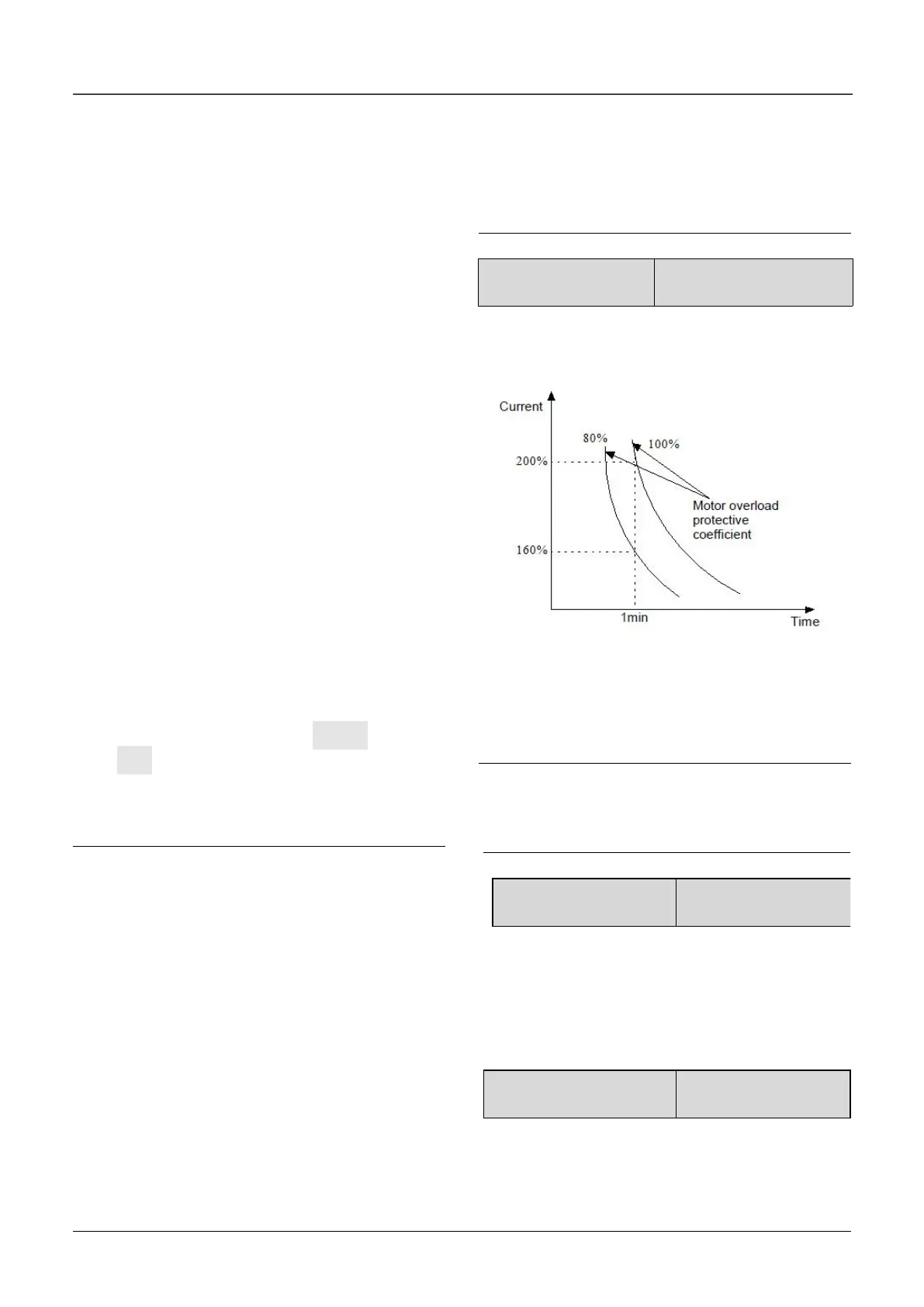
In order to apply effective overload protection to
different kinds of motors, the Max. output current of
the drive should be adjusted as shown in Fig. 6-34.
Fig.6-34 Motor’s overload protection coefficient
This parameter can be set according to the user’s
requirement. In the same condition, set b0.12 to a
lower value if the user need fast protection for
overload of motor, otherwise set it to a bigger value.
Note:
If the motor’s rated current does not match that of
the drive, motor’s overload protection can be
realized by setting b0.12.

 Loading...
