4.1.3 Wiring of VFD for Basic Operation
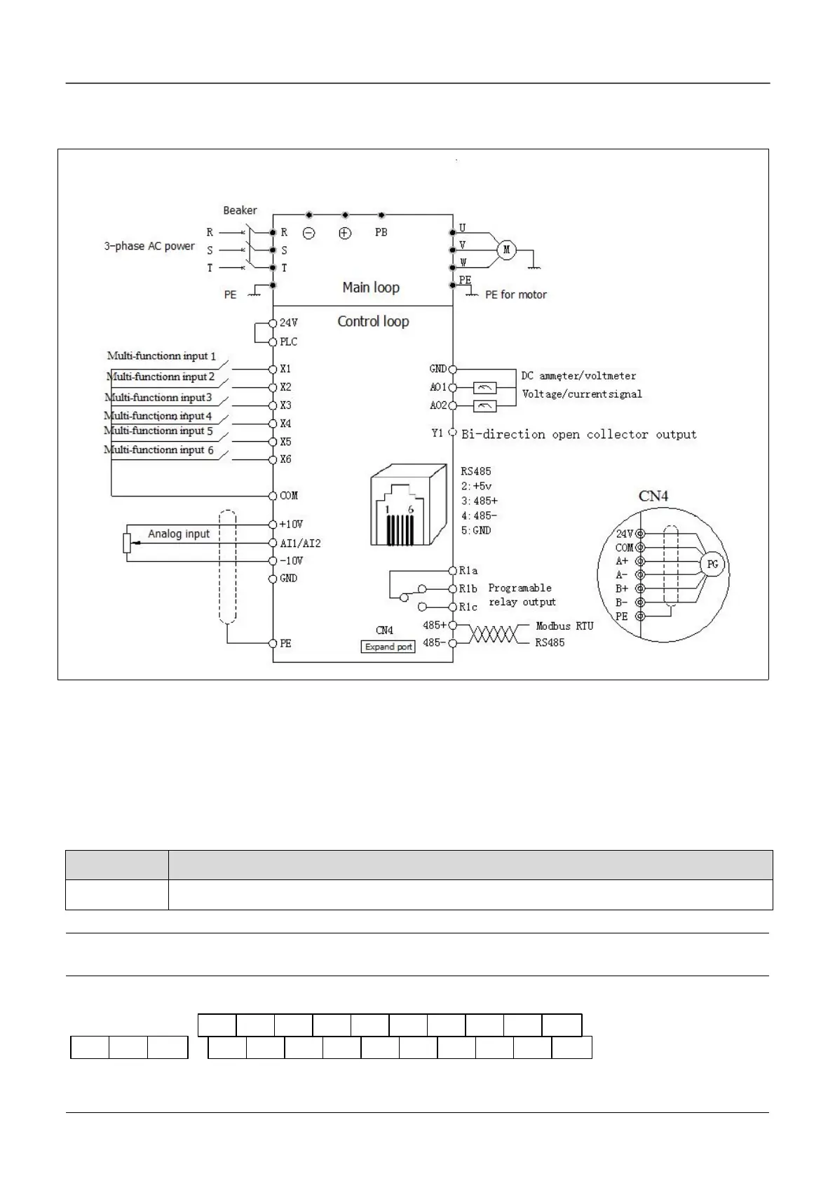
Applicable model: FV20-4T-0055G /0075L
Fig.4-1 Basic wiring chart
4.2 Wiring and configuration of control circuit
4.2.1 Wiring of control circuit terminal.
Wire the terminals correctly before using the Drive. Refer to the table 4-2 for control circuit terminal function
Table 4-2 Control circuit terminal function
Analog input and output terminal, RS232 and RSRS485 communication port
Note
It is recommended to use cables bigger than 1mm2 to connect to the terminals.
Arrangement of control circuit terminals is as follows
X1 X2 X3 X4 X5 COM 10V GND AI1 AI2
Y1 COM X6 24V PLC AO1 AO2 GND
485+
485-
Fig.4-2 Arrangement of control terminals

 Loading...
