Refer to table 4-2 and 4-3 for description of each terminal
Table 4-3 function list of each list
PE terminal connected to shielding
layer. 485 communication cable, Analog
signal cable, motor power cable shield
can be connected to this terminal here
Connected to PE terminal of
main loop inside
Provide +10V power supply
Maximum current output is
5mA
GND for analog signal and 10V power
supply
Isolated from COM and CME
inside
Can accept analog voltage or current
input, jumper AI1 can select voltage or
current input mode.(Reference ground:
GND)
Input voltage range:0~10V
(Input impedance 45kΩ)
Resolution:1/4000
Input current range:
0mA~20 mA,
Resolution:1/2000
(Need jumper)
Can accept analog voltage or current
input, jumper AI2 can select voltage or
current input mode. (Reference
ground:GND)
Providing analog voltage or current
output, they are selected by the jumper
AO1. The default setting is output
voltage, refer to the function code A6.30
for detail. (Reference ground: GND)
Voltage output range:
0V~10V
Current output range:
0/4~20mA
Providing analog voltage or current
output, they are selected by the jumper
AO2. The default setting is output
voltage, refer to the function code A6.31
for detail. (Reference ground: GND)
Voltage output range:
0V~10V
Current output range:
0/4~20mA
Standard RS-485
communication port, please
use twisted-pair cable or
shielded cable.
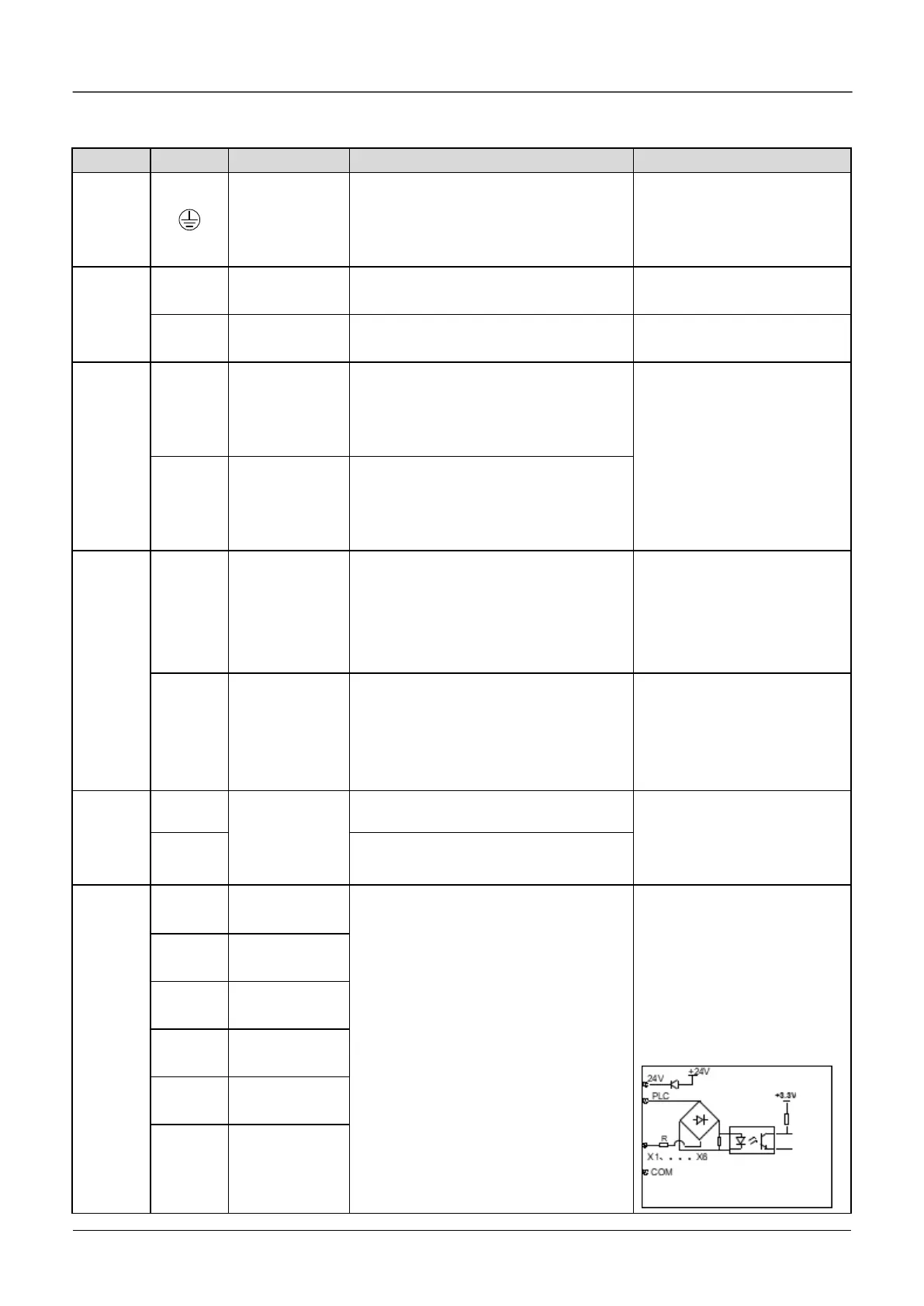
Multi-
function
input
terminal
Multi-function
input terminal 1
Can be defined as multi-function digital
input terminal.(Refer to the A6 group,
form A6.00 to A6.05)
Optocoupler isolation input
Input resistor: R=3.3kΩ
Maximum frequency input of
X1~X6: 200Hz
Maximum input frequency of
X6: 100kHz
Input voltage range:2~30v
Multi-function
input terminal 2
Multi-function
input terminal 3
Multi-function
input terminal 4
Multi-function
input terminal 5
Multi-function
input terminal 6
 Loading...

