b1.01 V/F frequency value
F3 of motor 1
b1.02 V/F voltage value V3
of motor 1
b1.03 V/F frequency value
F2 of motor 1
b1.04 V/F voltage value V2
of motor 1
b1.05 V/F frequency value
F1 of motor 1
b1.06 V/F voltage value V1
of motor 1
This group of parameters define the V/F setting
modes of FV20 so as to satisfy the requirements of
different loads. 3 preset curves and one
user-defined curve can be selected according to the
setting of b1.00.
If b1.00 is set to 1, a 2-order curve is selected, as
shown in Fig. 6-35 as curve 1;
If b1.00 is set to 2, a 1.7-order curve is selected, as
shown in Fig. 6-35 as curve 2;
If b1.00 is set to 3, a 1.2-order curve is selected, as
shown in Fig. 6-35 as curve 3;
The above curves are suitable for the
variable-torque loads such as fan & pumps. You
can select the curves according to the actual load
so as to achieve best energy-saving effects.
Fig.6-35 Torque-reducing curve
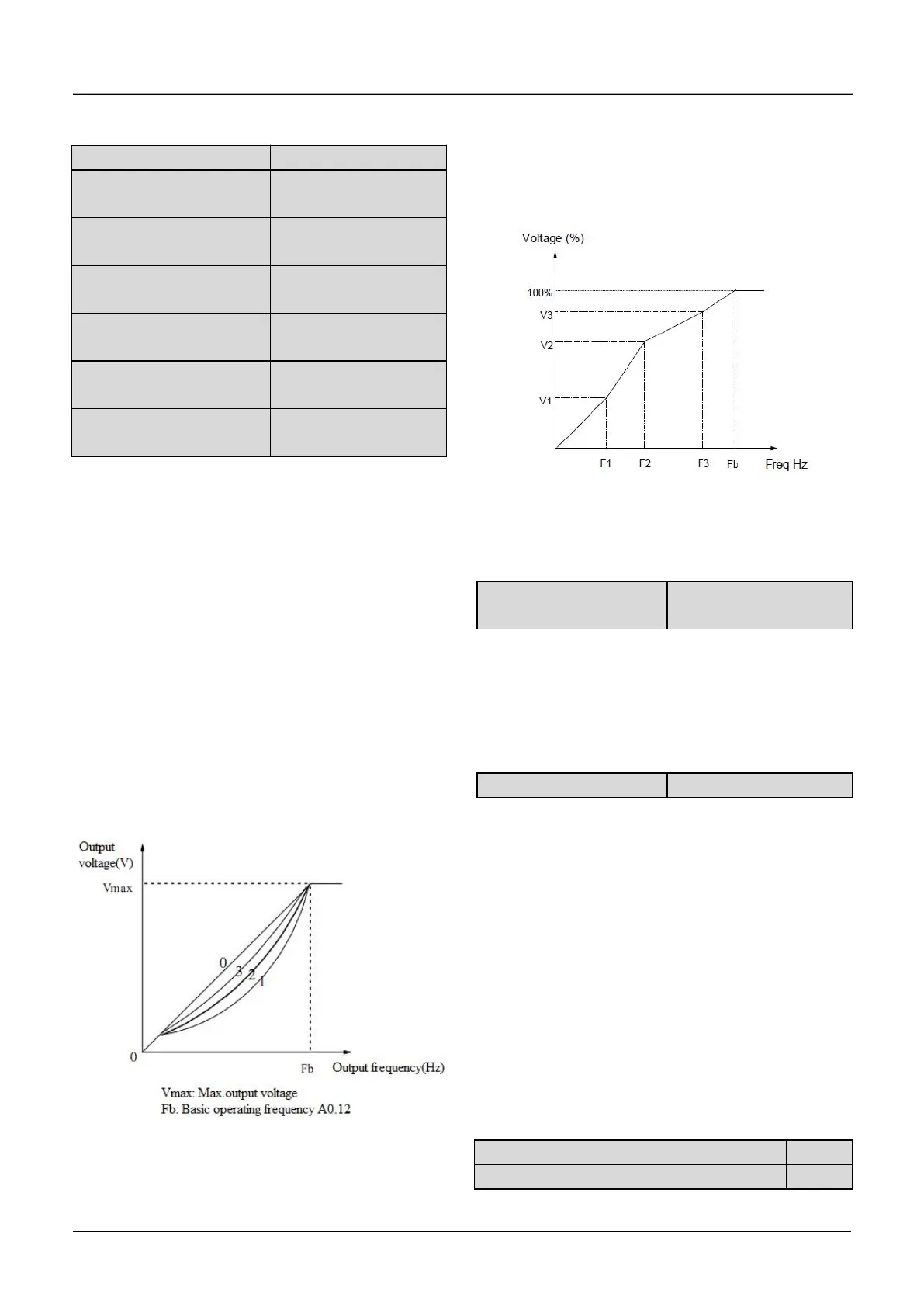
If b1.00 is set to 0, you can define V/F curve via
b1.01~b1.06, as shown in Fig. 6-36. The V/F curve
can be defined by connecting 3 points of (V1,F1),
(V2,F2) and (V3, F3), to adapt to special load
characteristics.
Default V/F curve set by factory is a direct line as
show in Fig. 6-35 as curve 0.
Fig.6-36V/F curve defined by user
b1.07 Cut-off point used
for manual torque boost
b1.07 defines the ratio of the cut-off frequency used
for manual torque boost to the basic operating
frequency (defined by A0.12), as shown in Fig. 6-36
as Fz. This cut-off frequency adapts to any V/F
curve defined by b1.00.
0: Disable
1: Enable all the time
2: Disabled in Dec process
AVR means automatic voltage regulation.
The function can regulate the output voltage and
make it constant. Therefore, generally AVR function
should be enabled, especially when the input
voltage is higher than the rated voltage.
In Dec-to-stop process, if AVR function is disabled,
the Dec time is short but the operating current is big.
If AVR function is enabled all the time, the motor
decelerates steadily, the operating current is small
but the Dec time is prolonged.
b1.09 VF Output Voltage Selection
b1.10 VF Output Voltage Offset Selection
V1~V3: Voltage of sections 1~3
F1~F3: Freq of sections 1~3
Fb
:
Basic operating frequency of A0.12

 Loading...
