C2.06 Step 3 operating time
C2.07 Step 4 setting mode
selector
C2.08 Step 4 operating time
C2.09 Step 5 setting mode
selector
C2.10 Step 5 operating time
C2.11 Step 6 setting mode
selector
C2.12 Step 6 operating time
C2.13 Step 7 setting mode
selector
C2.14 Step 7 operating time
C2.15 Step 8 setting mode
selector
C2.16 Step 8 operating time
C2.17 Step 9 setting mode
selector
C2.18 Step 9 operating time
C2.19 Step 10 setting mode
selector
C2.20 Step 10 operating time
C2.21 Step 11 setting mode
selector
C2.22 Step 11 operating time
C2.23 Step 12 setting mode
selector
C2.24 Step 12 operating time
C2.25 Step 13 setting mode
selector
C2.26 Step 13 operating time
C2.27 Step 14 setting mode
selector
C2.28 Step 14 operating time
C2.29 Step 15 setting mode
selector
C2.30 Step 15 operating time
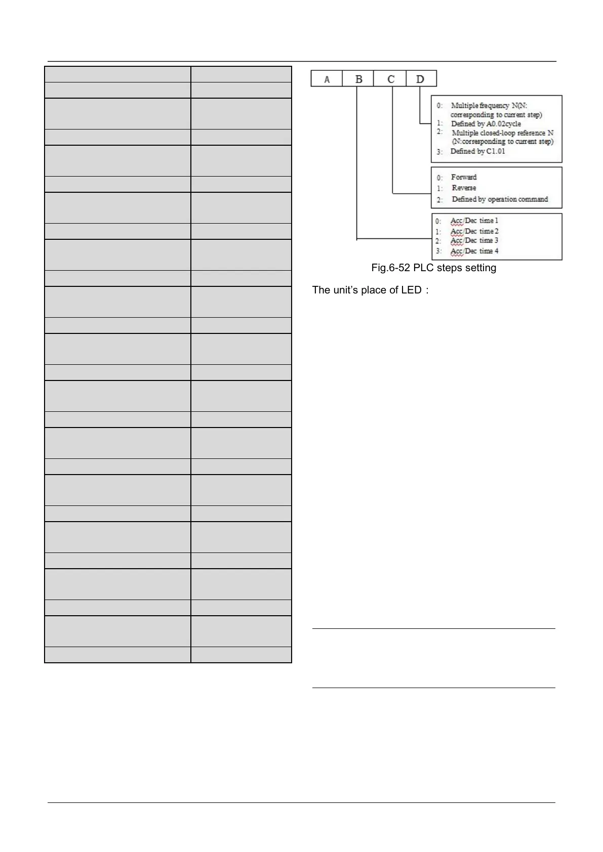
C2.01~C2.30 are used to set the operating
frequency, direction, Acc/Dec time and operating
time for PLC function. Here takes C2.01 as example,
as shown in Fig.6-52.
Fig.6-52 PLC steps setting
The unit’s place of LED:
0 : Multiple frequency N (N : corresponding to
current step)The frequency of current step depends
on the multiple frequency N. About the details of
multiple frequency setting, please refer to Group
C0.
1: Defined by A0.02.
Use A0.02 to set the frequency of current step.
2 : Multiple closed loop reference N (N :
corresponding to current step) The frequency of
current step depends on the multiple closed loop
reference N. About multiple closed loop setting,
please refer to C1.19~C1.33.
3: Defined by C1.01.
PLC runs in process closed loop mode, the closed
loop reference is defined by C1.01.
Ten’s place of LED:
0: Forward
Set the direction of current step as forward
1: Reverse
Set the direction of current step as reverse
2: Defined by operation command
The direction of current step is defined by the
operation command of terminals.
Note:
If the operation direction of current step can not be
confirmed, then it will continue the previous
direction.
6.16 Group C3
The swing function of the textile swing frequency
function is suitable for textile, chemical fiber and

 Loading...
