Fig.6-48 Keep final states after single cycle
3. Continuous cycle
As shown in Fig.6-49, the drive will continue next
cycle after finishing one cycle, and stop when there
is stop command.
Fig.6-49 Continuous cycle
The ten’s place of LED: Start modes
0: Start from first step
If the drive stop while it was running (Caused by
stop command, fault or power failure), then it will
start from first step when it restart.
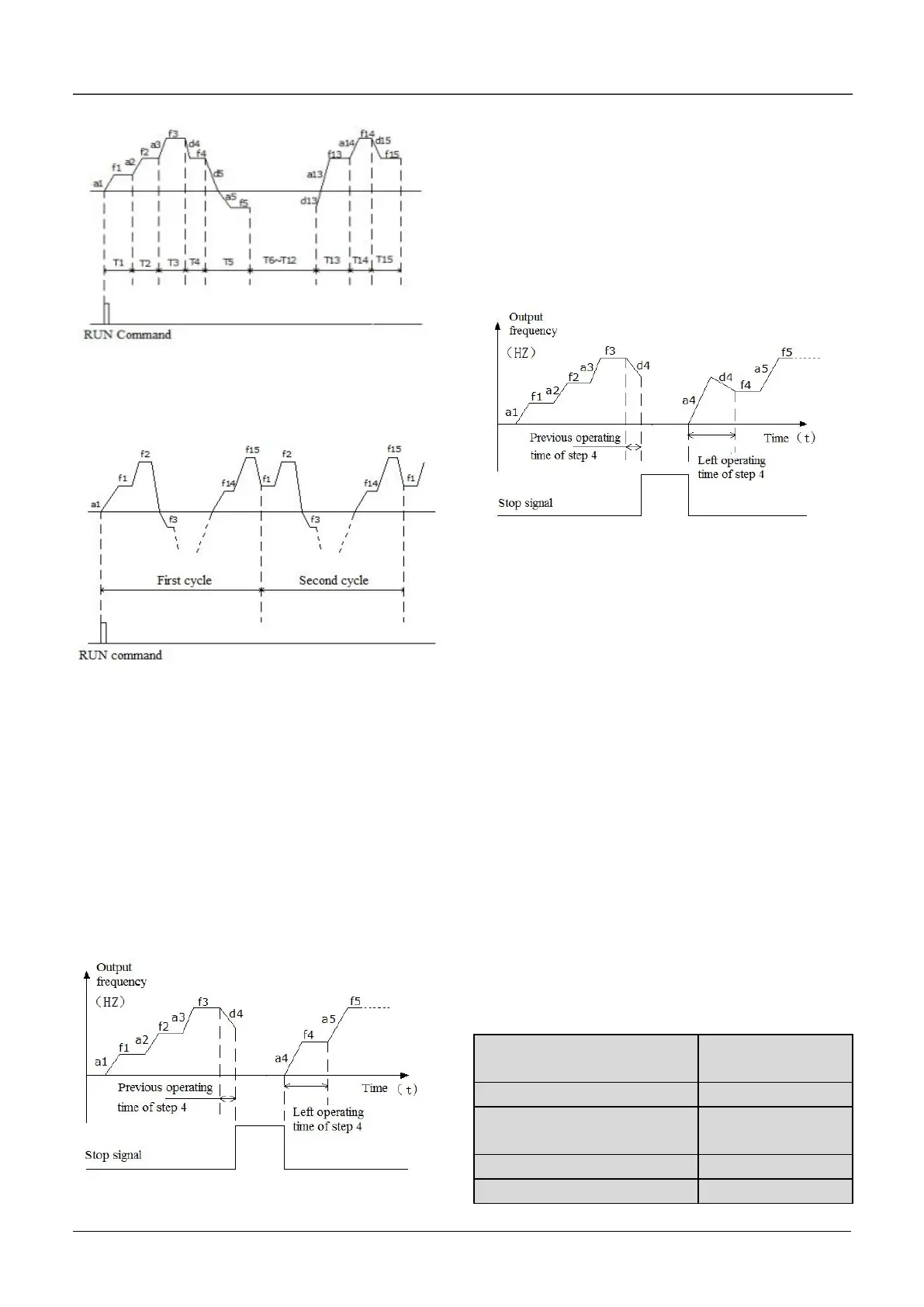
1: Start from the step before stop (or alarm)
If the drive stop while it was running(Caused by stop
command or fault), then it will record the operating
time of current step, and start from this step and
continue the left operating time when it restart, as
shown in Fig.6-50.
Fig.6-50 Start mode 1 of PLC function
2. Start from the step, frequency before stop (or
alarm)
If the drive stop while it was running(Caused by stop
command or fault),it will record the operating time of
current step and also record the operating
frequency, then when it restart, it will return to the
operating frequency before stop and continue the
left operating time, as shown in Fig.6-51.
Fig.6-51 Start mode 2 of PLC function
Hundred’s place of LED: Save after power off
0: Not save
The drive will not save the PLC operating status
after power off. It will start from first step after power
on again.
1: Save the segment frequency after power off
It will save the PLC operating status including step,
operating frequency and operating time, then it will
restart according the setting in ten’s place of LED
when power on again.
Thousand’s place of LED : Time unit selector of
each step
0: Second
Each steps will use second as the unit of operating
time.
1: Minute
Each steps will use minute as the unit of operating
time. This unit selector is only valid for PLC
operating time.

 Loading...
