This parameter is used to display the status of X1~
X6.0 indicates OFF status,1 indicates ON status.
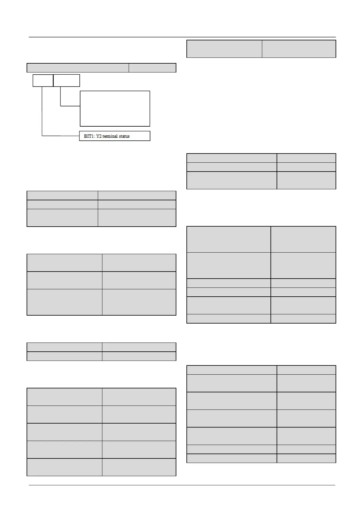
d0.15 Output terminals status
Fig.6-49 Output terminal status
This parameter is used to display the status of
output terminals. When there is signal output, the
corresponding bit will be set as 1.
d0.18 Keyboard
potentiometer input
d0.16~d0.18 are used to display the analog input
value before regulation.
d0.19 Percentage of AI1
after regulation
d0.20 Percentage of AI2
after regulation
d0.21 Percentage of
Keyboard potentiometer
after regulation
d0.19~d0.21 are used to display the percentage of
analog input after regulation.
d0.22、d0.23 are used to display the percentage of
analog output that corresponding to the full range.
d0.24 Process close-loop
reference
d0.25 Process close-loop
feedback
d0.26 Process close-loop
error
d0.27 Process close-loop
output
d0.28 Temperature of
heatsink 1
d0.29 Temperature of
heatsink 2
Temperature of heatsink 1 is the temperature of
IGBT modules. Different IGBT modules have
different over-temperature threshold.
Temperature of heatsink 2 is the temperature of
rectifier.
The drive of 30kW or below does not detect this
temperature.
Temperature display range:0~100℃.Accuracy:
5%
d0.30 Total conduction time
d0.31 Total operating time
d0.32 Total fan’s operating
time
d0.30 ~ d0.32 define the drive’s total conduction
time, operating time and fan’s operating time after
production.
d0.33 ASR controller output
-300.0~300.0%
(Corresponding to
rated torque of motor
-300.0~300.0%
(Corresponding to
rated torque of motor
d0.37 Zero offset of
Keyboard potentiometer
d0.35~d0.45 is read only.
6.20 Group d1
d1.01 Bus voltage of the latest
failure
d1.02 Actual current of the
latest failure
d1.03 Operation frequency of
the latest failure
d1.04 Operation status of the
latest failure
 Loading...

