A6.24~A6.25 is a complement to the No.3 function
in Table 6-6.
Their functions are the same. Take A6.22 ~ A6.23
for example:
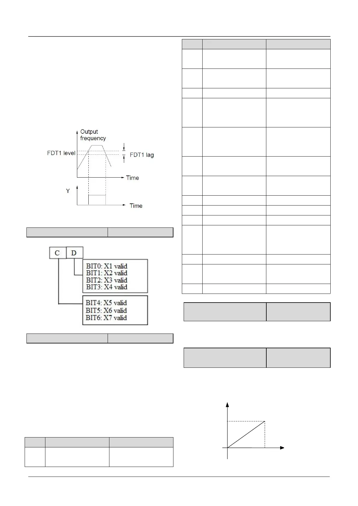
When the drive’s output frequency reaches a
certain preset frequency (FDT1 level), it outputs an
indicating signal until its output frequency drops
below a certain frequency of FDT1 level (FDT1
level-FDT1 lag), as shown in Fig. 6-27.
Fig.6-27 FDT level
A6.26 Virtual terminal setting
0~50: Y is used as Y terminal output, its function is
the same as Table 6-6.
51~88: Y function.
Pulse frequency of Y : 0 ~ Max. pulse output
frequency (Defined in A6.26).
The linear relationship between the displaying
range and the output values of Y is shown as Table
6-7.
Table 6-7 Displaying range of Y terminal
Preset frequency
(After Acc/Dec)
0~2 times of
motor’s rated
current
0~3 times of
motor’s rated
current
0~3 times of
motor’s rated torque
0~1.2 times of
drive’s rated voltage
Keyboard
potentiometer
Voltage
Percentage of host
computer
A6.28 Max. output pulse
frequency
This parameter defines the permissible maximum
pulse frequency of Y.
A6.29 Center point of pulse
output selection
This parameter defines different center point mode
of Y pulse output.
0:No center point. Shown as following figure:
Fig.6-28 No center point mode
 Loading...

