voltage is lower than the low voltage limit, and the
LED displays “P.oFF”.
6: External stopping command (EXT)
The terminal outputs the indicating signal if the drive
outputs tripping signal caused by external fault
(E015).
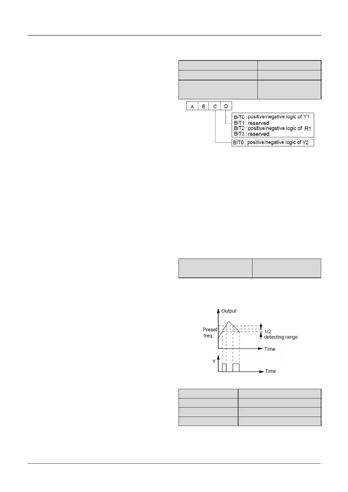
7: High limit of frequency (FHL)
The terminal outputs the indicating signal if the
preset frequency is higher than upper limit of
frequency and the operating frequency reaches the
upper limit of frequency.
8: Lower limit of frequency (FLL)
The terminal outputs the indicating signal if the
preset frequency is higher than lower limit of
frequency and the operating frequency reaches the
lower limit of frequency.
9: Zero-speed running
The terminal outputs the indicating signal if the
drive’s output frequency is 0 and the drive is in
operating status.
10~11:Reserved.
12: PLC running step finish signal
In PLC running mode, when it finishes the current
step, it will output signal(Single pulse with width
500ms).
13: PLC running cycle finish signal
In PLC running mode, when it finishes one cycle, it
will output signal(Single pulse with width 500ms).
14. Swing limit
In Swing mode, if the swing frequency is higher than
upper limit or lower than lower limit, then it will
output a signal.
15: drive ready (RDY)
If RDY signal is output, it means the drive has no
fault,
its DC bus voltage is normal and it can receive
starting command.
16: Drive fails
The terminal outputs the indicating signal if the drive
has faults.
17~18: Reserved.
19:Torque limiting
The terminal outputs the indicating signal if the
torque reach drive torque limit or brake torque limit.
20:Drive running forward/reverse
Fig.6-25 Output terminal’s positive and negative logic
A6.20 defines the output terminal’s positive and
negative logic .
Positive logic:Terminal is enabled if it is connected
to the common terminal;
Negative logic : Terminal is disabled if it is
connected to the common terminal;
If the bit is set at 0, it means positive logic; if set at 1,
it means negative logic.
Note:A6.18 is only valid when the function of terminal
R1 is activated.
 Loading...

