A6.13 defines the input terminal’s positive and
negative logic
Positive logic : Terminal Xi is enabled if it is
connected to the common terminal;
Negative logic : Terminal Xi is disabled if it is
connected to the common terminal;
If the bit is set at 0, it means positive logic; if set at 1,
it means negative logic. For example:
If X1~X4 are required to be positive logic, X5~X6
are required to be negative logic, settings are as
following:
Logic status of X4~X1 is0000, and the hex value is
0.
Logic status of X6~X5 is111, and the hex value is 7.
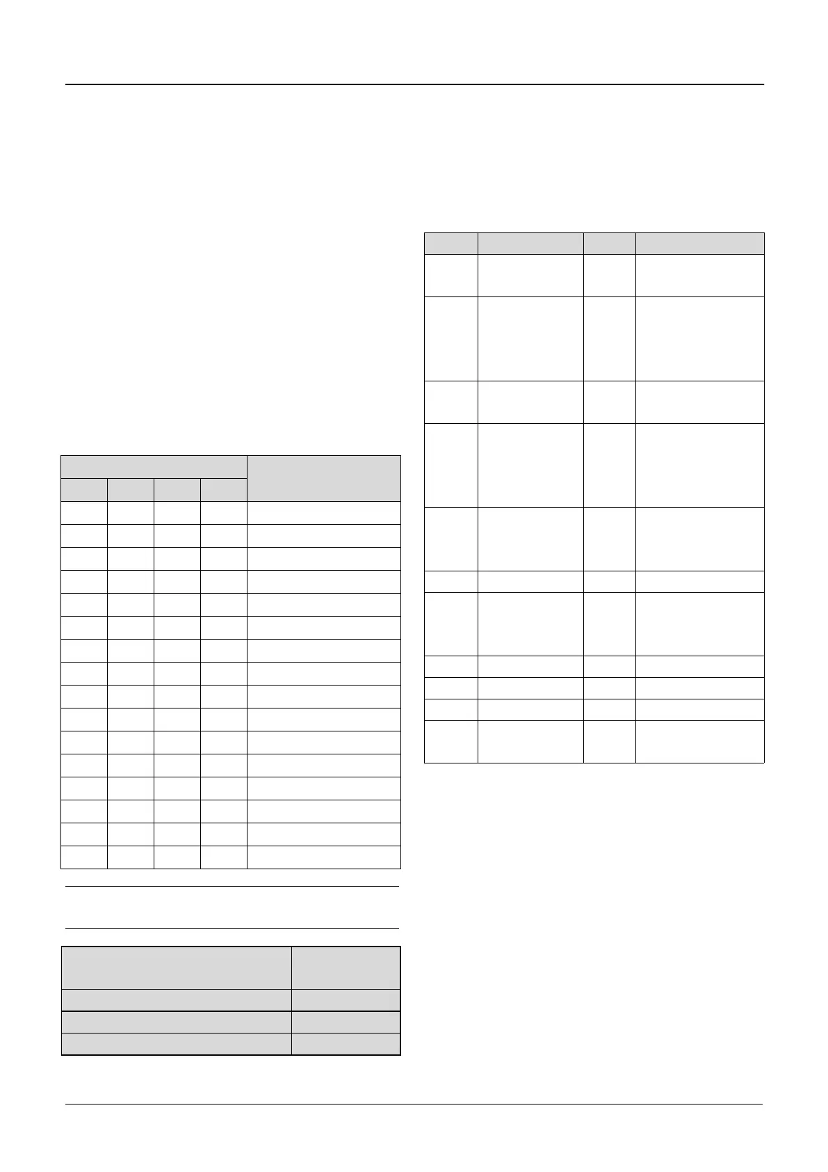
So A6.13 should be set as 70. Refer to Table 6-5.
Table 6-5 Conversion of binary code and hex value
Hex value
(Displaying of LED)
Note:
Factory setting of all the terminals is positive logic.
A6.14 Bi-direction open-collector
output terminal Y1
A6.16 Output functions of relay R1
Refer to chapter 3 for the output characteristics of
Y1 that are bi-direction open-collector output
terminal and the relay’s output terminal. Table 6-6
shows the functions of the above 2 terminals. One
function can be selected repeatedly.
Table 6-6 Functions of output terminals
Drive running
signal (RUN)
Frequency arriving
signal (FAR)
Frequency
detection
threshold
(FDT1)
Frequency
detection threshold
(FDT2)
Low voltage
lock-up signal (LU)
External
stopping
command
(EXT)
High limit of
frequency (FHL)
Lower limit of
frequency
(FLL)
PLC running
step finish
signal
PLC running cycle
finish signal
Drive running
forward/reverse
The instructions of the functions in Table 6-6 as
following:
0: Drive running signal (RUN)
When the drive is in operating status, there will be
running indication signal output by this terminal.
1: Frequency arriving signal (FAR)
See A6.19.
2: Frequency detection threshold (FDT1)
See A6.20~A6.21.
3: Frequency detection threshold (FDT2)
See A6.22~A6.23.
4: Reserved.
5: Low voltage lock-up signal (LU)
The terminal outputs the indicating signal if the DC bus
 Loading...

