Terminal Xf, Xr, Xi is the multi-function input
terminal of X1~X6. At this time, the function of this
terminal should be defined as No.1 (Forward) No.2
(Reverse) No.5 function (3-wire operation). First,
set the key SB1 in normal close status to make this
function(3-wire operation mode 2) enable. Second,
press the key SB2 once to give Xf a pulse signal
( ) then the running direction is forward, at
this moment, the key K is in normal open status.
Last but not least, make the key K in normal close
status, then the running direction will be reverse.
Just need to switch the status of key K, will the
direction be changed.
4: 2-wires operation mode 3
In this mode, if drive has been already set as start by
terminal control, and the terminal is already enable,
then when drive power on, it will start immediately.
Please be carefully to use this function.
A6.10 Max. frequency of
input pulse
This parameter is used to set the max. frequency of
input pulse when X6 is defined as pulse input.
A6.11 Center point of pulse
setting selection
This parameter defines different modes of center
point when X6 is defined as pulse input.
0: No center point.As shown in Fig.6-21.
Fig.6-21 No center point mode
All the corresponding values of pulse input
frequency are positive.
1: Center point mode 1.
Fig.6-22 Center point mode 1
There is a center point in pulse input. The value of
the center point is a half of max. frequency of input
pulse(A6.10).The corresponding value is positive
when the input pulse frequency is less than center
point.
2: Center point mode 2.
There is a center point in pulse input. The value of
the center point is a half of max. frequency of input
pulse(A6.10).The corresponding value is positive
when the input pulse frequency is greater than
center point.
Fig.6-23 Center point mode 2
A6.12 Filter of pulse input
This parameter defines the filter time of pulse input.
The bigger of the filter time, the slower of the
frequency changing rate of pulse input.
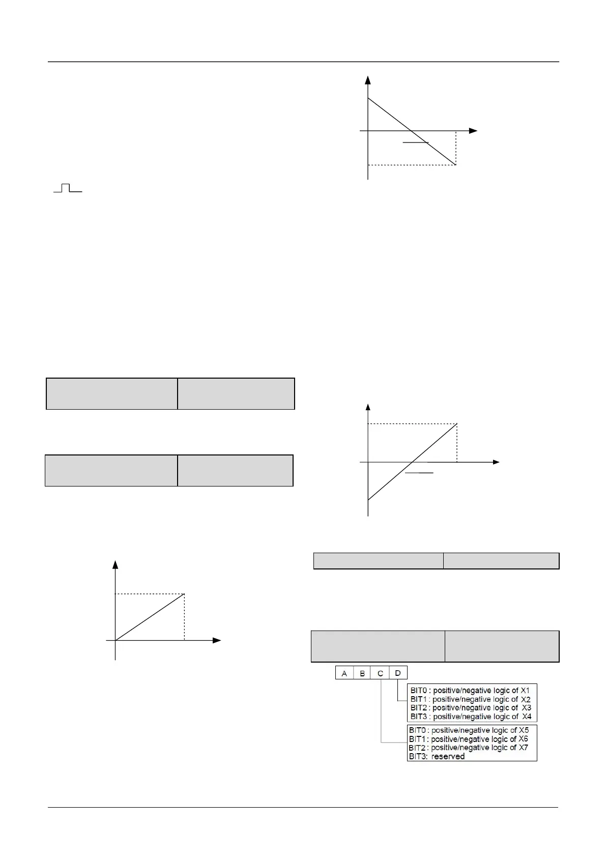
A6.13 Input terminal’s
positive and negative logic
Fig.6-24 terminal’s positive and negative logic

 Loading...
