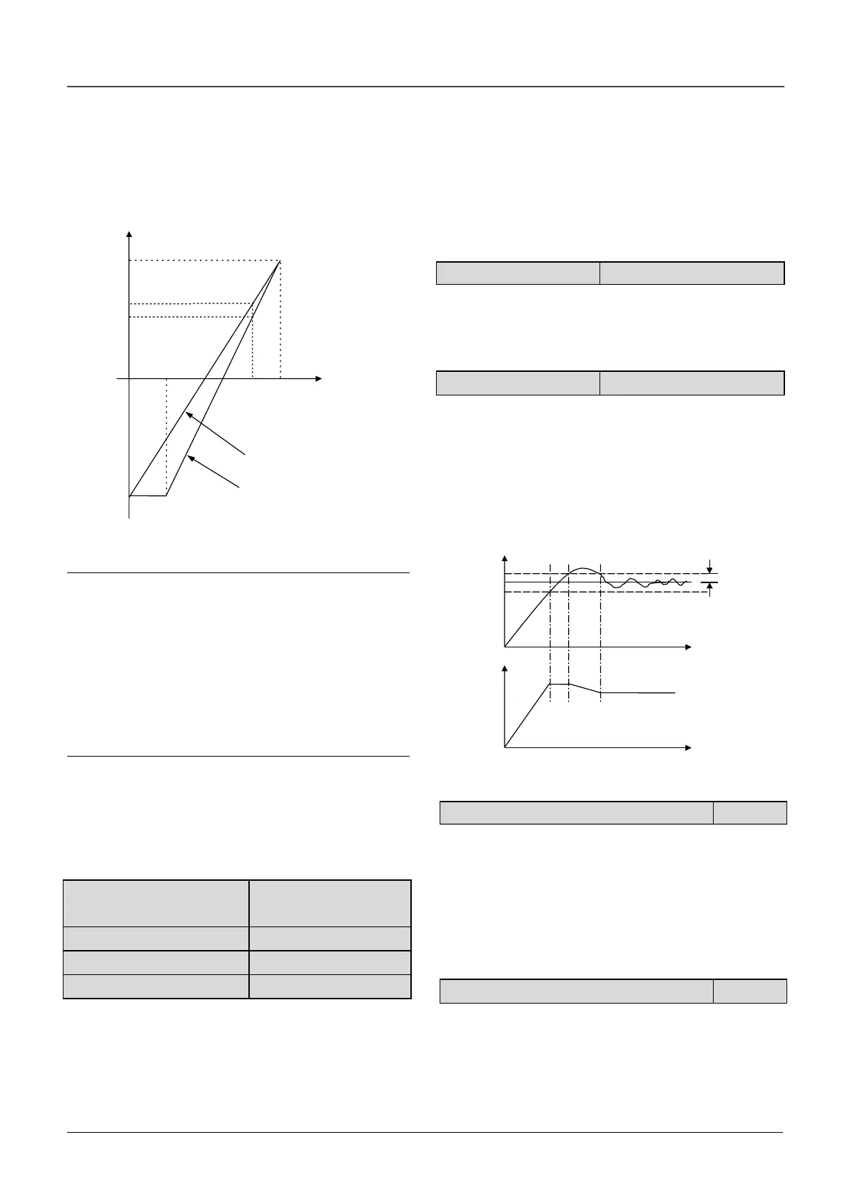
The regulation relationship between C1.05,C1.07(in
Fig.6-41) and reference is shown in Fig.6-43.When
the analog input 6V,if C1.05 = 0 % and C1.07 =
100%,then adjusted value is 60%.If C1.05=25%
and C1.07 = 100% , then the adjusted value is
46.6%.
Fig.6-43 Regulation curve of reference
Note:
1.Fig.6-43,0%~100% in X axis is corresponding
to analog input -10V~10V,10V of analog input is
corresponding to 100%,and-10V is corresponding
to 0%,6V is corresponding to 80%.
2.If the analog type is current input, because of the
current input range is 4~20mA,then the range of X
axis is 50%~100%.
3.The adjusted value can be observed in d0.24.
The regulation relationship between C1.06, C1.08
(in Fig.6-41) and feedback is similar to reference
regulation. Its adjusted value can be observed in
d0.25.
C1.09 Proportional gain
KP
C1.11 Differential gain Kd
The bigger the proportional gain of KP, the faster
the response, but oscillation may easily occur.
If only proportional gain KP is used in regulation, the
error cannot be eliminated completely. To eliminate
the error, please use the integral gain Ki to form a PI
control system. The bigger the Ki, the faster the
response, but oscillation may easily occur if Ki is too
big.
The sampling cycle T refers to the sampling cycle of
feedback value. The PI regulator calculates once in
each sampling cycle. The bigger the sampling cycle
the slower the response.
This parameter defines the filter time of the
close-loop output (Frequency or torque).The bigger
the output filter, the slower the response.
This parameter defines the max. deviation of the
output from the reference, as shown in Fig. 6-44.
Close-loop regulator stops operation when the
feedback value is within this range. Setting this
parameter correctly is helpful to improve the system
output accuracy and stability.
C1.15 Close-loop regulation characteristic
0: Positive
Set C1.15 to 0 if the motor speed is required to be
increased with the increase of the reference.
1: Negative
Set C1.15 to 1 if the motor speed is required to
decrease with the increase of the reference.
C1.16 Integral regulation selection
0 : Stop integral regulation when the frequency
reaches the upper and lower limits
1 : Continue the integral regulation when the
frequency reaches the upper and lower limits

 Loading...
