A0.03 Set the operating
frequency in digital mode
Range: Lower limit of
frequency ~upper limit of
frequency【50.00Hz】
When the main reference frequency is set in digital
mode(A0.02 =0), this setting of A0.03 is the drive’s
initial frequency value.
A0.04 Methods of inputting
operating commands
FV20 has two control modes.
0: Panel control: Input operating commands via
panel
Start and stop the drive by pressing RUN, STOP
and M on the panel.
1: Terminal control: Input operating commands
via terminals.
Use external terminals Xi(Set function code
A6.00~A6.06 to 1 and 2),M Forward, M Reverse to
start and stop the drive.
2:Modbus communication.
A0.05 Set running direction
This function is active in panel control mode , and
inactive in terminal control mode.
0: Forward
1: Reverse
Default value of Acc/Dec time 1:
2kW or below:6.0S
30kW~45kW:20.0S
45kW or above:30.0S
Acc time is the time taken for the motor to
accelerate from 0Hz to the maximum frequency (as
set in A0.08).
Dec time is the time taken for the motor to
decelerate from maximum frequency (A0.08) to
0Hz.
FV20 series VFD has defined 4 kinds of Acc/Dec
time.(Here only Acc/Dec time 1 is defined, and
Acc/Dec time 2~4 will be defined in A4.01~A4.06),
and the Acc/Dec time 1~4 can be selected via the
combination of multiple function input terminals,
please refer to A6.00~A6.06.
A0.08 Max. output
Frequency
Max{50.00,A0.11 upper limit of
frequency}~300.00Hz【50.00】
0~480V【VFD’s rating values】
A0.10 Upper limit of
frequency
A0.11 Lower limit of
frequency
A0.12 Basic
operating frequency
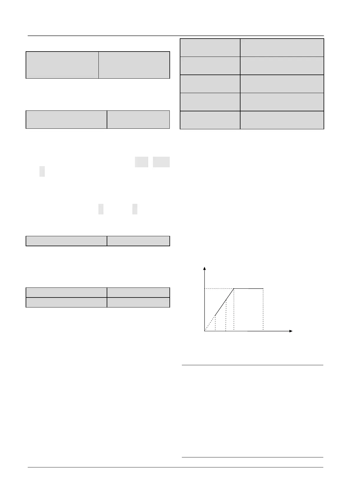
Max output frequency is the highest permissible
output frequency of the drive, as shown in Fig. 6-1
as F
max
;
Max output voltage is the highest permissible output
voltage of the drive, as shown in Fig. 6-1 as V
max
Upper limit of frequency is the highest permissible
operating frequency of the user setting, as shown in
Fig. 6-1 as F
H.
Lower limit of frequency is the lowest permissible
operating frequency of the user setting, as shown in
Fig.6-1 as F
L
.
As shown in Fig. 6-1 as F
b,
Basic operating
frequency is the Min. frequency when
the drive outputs the max voltage in V/F mode.
Fig.6-1 Characteristic parameters
Note:
1.Please set Fmax, F
H
and F
L
carefully according to
motor parameters and operating states.
2.F
H
and F
L
is invalid for JOG mode and auto tuning
mode.
3.Besides the upper limit of frequency and lower
limit of frequency,the drive is limited by the starting
frequency(A1.01),DC braking initial and hopping
frequency.(A1.06) and etc.
4.The Max. output frequency, upper limit frequency
and lower limit frequency is as shown in Fig.6-1.

 Loading...
