0: Dec-to-stop
After receiving the stopping command, the drive
reduces its output frequency according to the Dec
time, and stops when the frequency decreases to 0.
1: Coast-to-stop
After receiving the stopping command, the drive
stops outputting power immediately and the motor
stops under the effects of mechanical inertia.
2: Dec-to-stop+DC injection braking
After receiving the stop command, the drive
reduces its output frequency according to the Dec
time and starts DC injection braking when its output
frequency reaches the initial frequency of braking
process.
Refer to the introductions of A1.06~A1.09 for the
functions of DC injection braking.
A1.06 DC injection braking
initial frequency at stop
A1.07 Injection braking
waiting time at stop
A1.08 DC injection braking
current at stop
A1.09 DC injection braking
time at stop
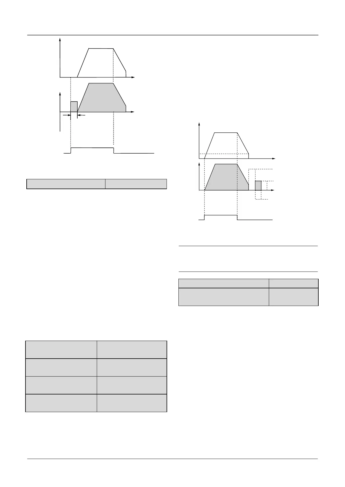
DC injection braking waiting time at stop : The
duration from the time when operating frequency
reaches the DC injection braking initial frequency
(A1.06) to the time when the DC injection braking is
applied.
The drive has no output during the waiting time. By
setting waiting time, the current overshoot in the
initial stage of braking can be reduced when the
drive drives a high power motor.
DC injection braking current at stop is a percentage
of drive’s rated current. There is no DC injection
braking when the braking time is 0.0s.
Initial Frequency
of braking
Fig.6-5 Dec-to-stop + DC injection braking
Note:
DC injection braking current at stop(A1.08) is a
percentage value of drive’s rated current.
A1.10 Restart after power failure
A1.11 Delay time for restart after
power failure
A1.10 and A1.11 decide whether the drive starts
automatically and the delay time for restart when
the drive is switched off and then switched on in
different control modes.
If A1.10 is set to 0, the drive will not run
automatically after restarted.
If A1.10 is set to 1, when the drive is powered on
after power failure, it will wait certain time defined by
A1.11 and then start automatically depending on
the current control mode, the drive’s status before
power failure and the command state when power
on. See Table 6-1.
Output
Voltage
(effective
Value)
 Loading...

