A3.18 Actual value
corresponding to the Min
reference of inflection point 1
of curve 4
A3.19 Min reference of curve 4
A3.20 Actual value
corresponding to the Min
reference of curve 4
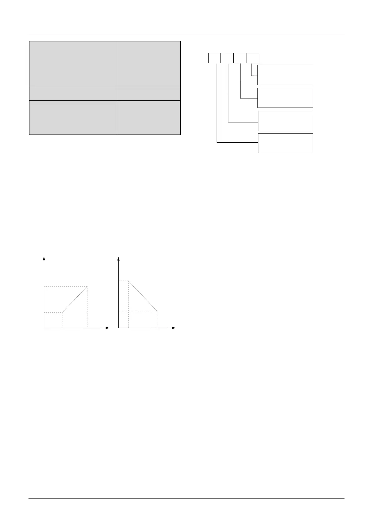
Reference frequency signal is filtered and amplified, and
then its relationship with the preset frequency is
determined by Curve 1,2,3 or 4. Curve 1 is defined by
A3.01 ~ A3.04.Curve 2 is defined by A3.05 ~
A3.08.Curve 3 is defined by A3.09~A3.12.Curve 4 is
defined by A3.13~A3.20. Take preset frequency as
example, positive and negative characteristics are shown
in Fig.6-8.In Fig.6-8,the inflection points are set the
same as the corresponding relationship of Min. or Max
reference.
Fig.6-8 Freq. coreesponding to Min. frequency
Analog input value(A) is a percentage without unit, and
100% corresponds to 10V or 20mA. Pulse frequency (P)
is also a percentage without unit, and 100% corresponds
to the Max pulse frequency defined by A6.10.
The time constant of the filter used by the reference
selector is defined in Group A6.
A3.00 is used to select the analog input curve and pulse
input curve,as show in Fig.6-9.
Fig.6-9 Frequency curve selection
For example, the requirements are:
1.Use the analog signal(AI1) input to set the
reference frequency;
2.Input signal: 0V~10V;
3.0.5V input signal corresponds to 50Hz reference
frequency, and 4V input signal corresponds to 10Hz
reference frequency, 6V input signal corresponds to
40Hz reference frequency, 10V input signal corresponds
to 5Hz reference frequency.
According to the above requirements, the parameter
settings are:
1)A0.02=1, select AI1 input to set the reference
frequency.
3)A3.00=0003, select curve 4.
4)A0.08=50.0kHz,set the Max output frequency to 50
Hz.
5)A3.13=10÷10×100%=100.0%, set the percentage
that the Max reference (10V) corresponds to 10V
6)A3.14=5.00Hz÷A0.08*100%, set the percentage that
the max input signal corresponds to the the reference
frequency
7)A3.15=6÷10×100%=60.0%,the percentage that
inflection2 reference(6V) of curve 4 corresponds to the
10V.
8)A3.16=40.00Hz÷A0.08*100%,set the percentage
that inflection2 reference (6V) corresponds to the
reference frequency.
Freq. coreesponding
To Min. frequency
Freq. coreesponding
To Max. frequency
 Loading...