Do you have a question about the Kolida K20s and is the answer not in the manual?
Provides an introduction to KOLIDA Instruments Co., Ltd. and the K20s system.
Details various applications of the K20s system, including control, highway, and marine surveys.
Highlights the key technical and functional features of the K20s positioning system.
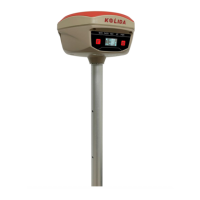
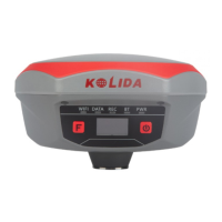
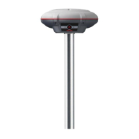
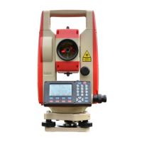
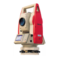
Identifies and describes the main physical components of the K20s receiver.
Explains how to operate the K20s receiver using its physical buttons and OLED display.
Details the components and ports located on the lower housing of the receiver.
Describes how to select the operating mode (Base, Rover, Static) on the K20s.
Explains how to configure various datalink options like UHF, Cellular, Bluetooth, and WiFi.
Allows configuration of system options like language, voice prompts, and self-check.
Guides users through configuring WiFi settings, including AP and Client modes.
Provides information on the currently used datalink for Base or Rover modes.
Explains the config mode for receiver debugging and problem diagnosis.
Describes the procedures for powering off or restarting the K20s receiver.
Introduces configuration and monitoring of K20s via WEB UI through WiFi or USB Ethernet.
Details accessing the K20s Web UI login page via IP address and entering credentials.
Explains the Status menu, which displays positioning, satellite tracking, and other information.
Covers general config, base, antenna, satellite setup, and receiver operation settings.
Displays and allows configuration of tracking satellites and their information.
Configures parameters for static mode, including storage, interval, and data format.
Provides interface to download collected raw data.
Covers general, serial port, TCP/IP, NTRIP, and data flow configurations.
Configures serial port and Bluetooth settings like baud rate and data flow.
Configures raw or navigation data upload to a server via TCP/IP.
Configures NTRIP performance for connecting to the internet.
Sets up rover to download corrections from a server via NTRIP.
Sets up base to upload corrections to a server.
Enables the receiver to act as a CORS system broadcasting corrections.
Configures the content and update rate of data flow output.
Configures internet access options like GSM/GPRS, WiFi, and Bluetooth.
Displays and configures receiver information and parameters for GPRS mode.
Configures WiFi settings, including AP and Client modes for internet access.
Manages Bluetooth connection status, MAC address, and paired devices.
Configures internet transmission ports for K20s customization and debugging.
Configures router parameters for receiver customization and debugging.
Tests the network status of K20s after connecting to the internet.
Configures radio parameters like baud rate, channel, power, and protocol.
Details procedures for updating the receiver and modem firmware online or locally.
Used to update firmware for modules like GNSS, radio, and network.
Manages user accounts, permissions, and login authority for the Web UI.
Provides assistance and access to the receiver's log book for status tracking.
Provides a basic introduction and overview of the T17N data collector.
Details the procedures for charging the T17N device via DC adapter or USB cable.
Guides on installing battery, SIM card, and storage card into the T17N.
Explains how to power on, power off, or reset the T17N device.
Guides on connecting the T17N to a PC using ActiveSync or Windows Mobile Device Center.
Details how to install programs onto the T17N from a PC.
Explains how to use the GNSSViewer application on the T17N for GPS operations.
Describes how to take photos using the T17N's camera function.
Guides on installing EGStar software and connecting the T17N to a computer.
Lists and describes the standard accessories included with the K20s receiver.
Describes the optional portable battery case SA6003 for extended power supply.
Lists and explains other essential cables like 7-pin to OTG and communication cables.
Details static measurement procedures, requirements, and scope.
Describes static measurements, their scope, and application in geodetic networks.
Outlines the step-by-step procedures for static measurements, from pre-measurement to project acceptance.
Provides important notes and tips for conducting static field operations.
Explains principles and considerations for designing GPS networks for surveying.
Details the procedure and importance of accurately measuring antenna height.
Explains RTK technology and methods for real-time kinematic measurements.
Details RTK operation using internal radio for base and rover stations.
Guides on setting up the base station in an optimal location and connecting components.
Explains how to start the base station using EGStar3.0 software or the Web UI.
Guides on setting up the rover station and connecting it to the controller.
Explains how to configure the rover receiver using EGStar3.0 and Web UI.
Explains RTK operation using an external radio for base station setup.
Guides on setting up the base station with an external radio and power supply.
Details radio settings for external radio communication, including channels and power.
Provides reference to the procedure for starting the base station with external radio.
Explains RTK operation using GPRS internet for base and rover stations.
Explains RTK operation using WiFi for stable and faster network connections.
Details the IMU sensor's capabilities for tilt survey without calibration, unaffected by magnetic environments.
Explains how to use the radio router feature for transferring corrections between rovers.
Details positioning accuracy for code differential, static, RTK, and network RTK.
Lists the physical dimensions and weight of the K20s receiver.
Describes the user interface elements like indicator lights, buttons, and screen.
Lists the input/output interfaces, including ports and Bluetooth standards.
Details the memory specifications, including internal and external storage.
Lists the supported operations like RTK rover/base and NTRIP.
Details operating and storage temperatures, humidity, and waterproof rating.
Specifies battery type, capacity, life, and external power requirements.
Lists UHF radio features like channels, frequency range, protocols, and working range.
Details cellular module compatibility with WCDMA, CDMA, LTE, and GPRS.
Lists WiFi standards, hotspot capabilities, and data link features.
Details the intelligent voice guide and supported languages.
Lists standard included components like receiver, charger, antenna, and software.
The unknown integer number of carrier phase cycles measured from satellite to receiver.
The connection line between two measurement points for simultaneous GPS data collection.
Satellite orbit parameters message released by the satellite demodulator.
An endpoint signal power to noise power ratio.
Interference loop skipping cycles, causing phase integer errors.
Modulation of a wave by frequency, amplitude, or phase relative to a reference value.
GPS coarse/acquisition code, a pseudo-random binary code for 1023 bit duplex.
GPS measurements using cross-satellite, cross-receiver, and cross-epoch techniques.
Determining relative coordinates by tracking the same GPS signal with multiple receivers.
Describes satellite geometry's contribution to dynamic positioning errors.
The ratio of the distance between foci to the distance between vertices in an ellipse.
Mathematical graphic formed by rotating an ellipse around its minor axis.
The position of celestial bodies over time, used in navigation.
The ratio of the difference between semi-major and semi-minor axes to the semi-major axis.
An equipotential surface of the Earth's gravity field, approximating mean sea level.
Delay of radio waves caused by the non-uniform ionosphere medium.
The radio frequency range from 390-1550MHz.
Positioning error caused by interference from multiple signal paths.
The period of collecting GPS data using two or more receivers simultaneously.
Calculated distance based on signal reception time and speed of light.
GPS receiver's RF mixer and IF channel for tracking carrier signals.
Satellite status relative to a user or group at a specific time.
Position measurement without considering receiver movement.
Warning about unauthorized modifications voiding operating authority.
Statement on compliance with FCC Rules, including conditions for operation.
| Model | K20s |
|---|---|
| Category | Measuring Instruments |
| Type | GNSS Receiver |
| Tilt sensor | Yes |
| IMU | Yes |
| Waterproof/Dustproof | IP67 |
| Data Update Rate | Up to 20 Hz |
| Weight | 1.2 kg |
| Supported constellations | GPS, GLONASS, BeiDou, Galileo |
| Positioning accuracy (RMS) | Horizontal: 8mm + 1ppm |
| Communication | Bluetooth, Wi-Fi, 4G |
| Storage Temperature | -40°C to +85°C |
| Power Supply | Lithium-ion battery |