Do you have a question about the Kolida KTS440 R Series and is the answer not in the manual?
Describes the instrument's capabilities and advantages.
Lists essential safety and handling guidelines for the instrument.
Details safety measures related to laser operation and product classification.
Explains how the instrument automatically corrects vertical angles based on tilt.
Describes how to use the display backlight for better visibility in dark conditions.
Details how to configure various instrument parameters based on measurement conditions.
Explains how to set the instrument's constant value, typically factory-set.
Describes how to adjust the contrast of the instrument's LCD screen for optimal readability.
Explains how to set or revise the instrument's date and time displayed in the status screen.
Provides explanations for automatic tilt compensation, parallax, and power-saving features.
Provides instructions on how to safely unpack and store the instrument.
Details the procedure for setting up the instrument on a tripod and leveling it.
Explains how to handle the instrument's battery, including removal, information, and recharging.
Describes the types of reflector prisms used and their purpose in measurements.
Details the procedure for attaching and detaching the instrument from the tribrach.
Explains how to adjust the eyepiece and set up the object for clear sighting.
Covers turning the instrument on/off and initial preparations before taking measurements.
Explains procedures for measuring horizontal and vertical angles.
Details how to measure the angle between two points and set the horizontal angle to zero.
Explains how to set the horizontal circle to a specific direction value using HSET or HOLD.
Explains how to switch between clockwise and counterclockwise horizontal angle displays.
Describes the procedure for performing repetition measurements for greater angle precision.
Explains how to display the gradient as a percentage using the ZA/% function.
Details necessary settings before performing distance measurements, including atmospheric and prism correction.
Explains how to check the reflected signal strength for accurate distance measurements.
Describes how to perform simultaneous angle and distance measurements.
Explains how to display and review recently measured distance and angle data.
Details how to output measured distance and angle data to a computer.
Explains how to input station coordinates, instrument height, and target height.
Describes how to load previously stored coordinate data from memory into the instrument.
Explains how to calculate and set the backsight azimuth angle using station and backsight coordinates.
Details finding target coordinates using measured distance and angle with station data.
Explains how to set out required points using measured angles, distances, or coordinates.
Details setting out points based on horizontal angle from a reference and distance from the instrument.
Explains how to perform setting-out for points not directly installable using REM.
Describes setting out points using pre-defined coordinates and horizontal angle/distance.
Explains setting parameters like temperature, pressure, and prism constant for distance measurement.
Explains measuring offset points positioned left/right or front/back of the target.
Describes measuring offset points on the right and left of the target to determine angles.
Explains finding a target point by installing two offset points on a line and measuring distances.
Details measuring distances to multiple targets using the MLM function.
Explains displaying the gradient between two points as a percentage.
Describes how to change the last measured point to the next starting point for measurement.
Explains how to re-measure from known points during resection.
Details the procedure for adding more known points during resection measurement.
Provides functions for road alignment design, including defining horizontal and vertical alignments.
Details how to manually enter or download horizontal alignment data (straight, arc, transition curves).
Explains how to modify existing alignment data, including points, straight lines, and curves.
Describes how to define vertical curve data, including chainage, elevation, and curve length.
Explains how to modify existing vertical curve data using chainage and other parameters.
Details transferring horizontal alignment data from a computer to the instrument.
Explains how to transfer vertical curve data from a computer to the instrument.
Describes how to delete horizontal alignment data stored in the instrument's memory.
Explains how to delete vertical curve data stored in the instrument's memory.
Covers performing alignment setting-out based on road design chainage and offset.
Details setting the station point by reading memory or manual keyboard entry of chainage/offset.
Explains two methods for setting the backsight point: by angle or by coordinate.
Describes the process of performing setting-out measurements after defining station and backsight points.
Explains performing slope setting-out as part of alignment setout, defining cut and fill slopes.
Covers settings related to JOB and memory management, including selection and deletion.
Details how to select, manage, and view JOBs for data recording.
Explains setting grid factors for coordinate calculations and distance adjustments.
Describes the procedure for renaming existing JOBs within the instrument.
Explains how to clear data from a designated JOB, noting prerequisites for deletion.
Details how to transfer JOB data from the instrument to a computer.
Explains how to transfer coordinate data from a computer to the instrument.
Describes how to input coordinate data directly into the current working JOB.
Explains how to register coordinate data in memory for later use as station, backsight, or known points.
Details manually entering coordinate data using the instrument's keypad.
Explains how to transfer coordinate data from external instruments via communication.
Describes how to transmit known point data from the instrument to other devices.
Covers methods for clearing coordinate data, either all at once or designated items.
Explains how to delete specific coordinate data entries by point number.
Details clearing coordinate data by searching for a specific point number.
Explains how to display coordinate data stored in the instrument's memory.
Describes how to save and register codes in memory for use during data recording.
Explains how to clear codes from the instrument's memory.
Describes how to display a list of codes stored in the instrument's memory.
Explains how to restore instrument parameters and clear all data to factory defaults.
Explains how to allocate soft keys in MEAS Mode to customize instrument operations.
Details how to set new key allocations, register them, and recall them.
Describes how to freely allocate up to 12 functions to soft keys for customized operation.
Explains how to recall previously registered soft key allocations (User 1, User 2, or Default).
Lists and describes various instrument parameters that can be changed.
Explains how to restore instrument parameters and clear all data to factory defaults.
Details inspection and adjustment procedures for the plate level bubble.
Covers inspection and adjustment of the circular level bubble.
Explains how to inspect and adjust the reticle for proper alignment.
Details the procedure for checking and adjusting the perpendicularity of the collimation line to the horizontal axis.
Explains how to inspect and compensate for the vertical index difference.
Covers adjusting the vertical index difference and setting the vertical angle 0 datum.
Explains how to confirm and adjust for horizontal axis error.
Details the inspection and adjustment procedure for the optical plummet.
Explains how to check and adjust the instrument constant (K).
Details checking and adjusting the alignment of collimation and photoelectric axes.
Covers inspection and adjustment for the reflectorless EDM function.
Explains how to tighten leveling screws if they become flexible.
Lists related accessories for use with reflectors.
| Brand | Kolida |
|---|---|
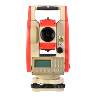
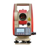
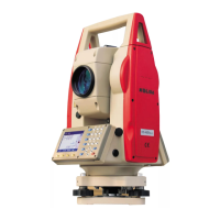
| Model | KTS440 R Series |
| Category | Measuring Instruments |
| Language | English |