171
The plate level and optical plummet in the adapter and tribrach should be checked, refer to Chapter 24.1
and 24.7.
2. Perpendicularity of the prism pole
As illustrated, mark ‘+’ on Point C, place the tine of the prism pole on the Point C and do not move
it during the inspection. Place the two feet tine of Bipod on Point E and F on the cross lines. Adjust
the two legs to make the bubble on the prism pole centered.
Set and level the instrument on Point A near the cross. Sight tine of Point C with the center of reticle, and
fix the Horizontal Clamp Screw. Rotate the telescope upward to make D near the horizontal hair. Flex the
prism pole Leg e to make the D in the center of reticle. Then both Point C and D are on the central line of
reticle.
Set the instrument on Point B on another cross lines. With the same way flexing the Leg f to make Point C
and D are on the central line of reticle.
Through the inspection by the instrument on Point A and B, Prism pole has been perpendicular. If then the
bubble offset from the center, adjust the three screws under circular vial to make the bubble centered, refer
to Chapter 20.2.
Check and adjust again until the bubble is in the center of the vial from both directions.
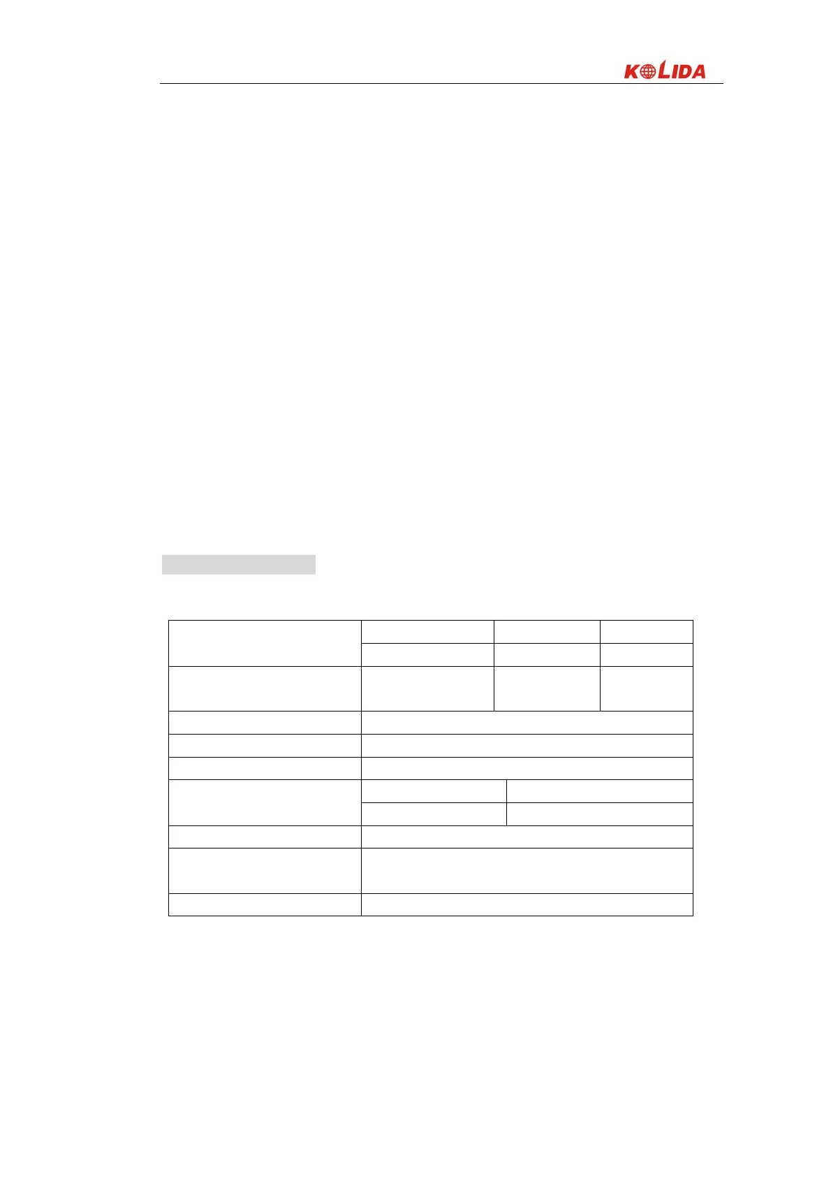
23. SPECIFICATION
Distance measurement
KTS-442/5 (R) KTS-442/5 (L) KTS-442/5
TYPE
Red visible laser Laser Infraed
carrier wave (only on
KTS-442/5(R))
0.650 – 0.690 μm
Measuring system Basic frequency 60MHZ
EDM type Coxial
Minimum display 1mm
Non-reflector
About 7×14 ㎜ / 20m
Laser facula
(only on KTS-442/5(R) )
With-reflector
About 10×20 ㎜ / 50m
Weather correction Manually input, Auto correction
Atmosphere reflection and earth
curve correction
Manually input, Auto correction
Prism constant correction Manually input, Auto correction
 Loading...