COOLING SYSTEM DESCRIPTION
The standard 830E engine is a Komatsu model
SDA16V1610 single stage turbocharged engine
equipped with aftercoolers.
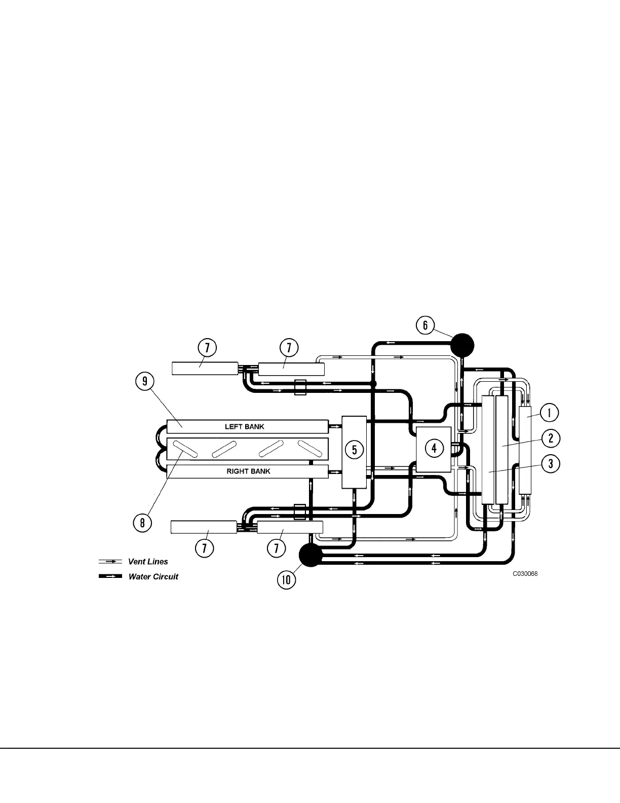
The engine cooling radiator assembly contains two
cores; A “low temperature” core (2, Figure 3-1) is
connected to the four aftercoolers (7). There are two
aftercoolers located on each cylinder bank. This
coolant is circulated by the engine’s LTA (Low Tem-
perature Aftercooler) water pump (6). The LTA ther-
mostats (4) begin to open at 115° F (46° C) and are
fully open at 135° F (57° C).
A second, “high temperature” core (3), located at
the rear of the radiator assembly is used for the
engine coolant circuit. In this circuit, the engine
water pump (10) circulates coolant through the
engine block (9) (heads, liners, internal oil coolers
etc.). The engine coolant thermostats (5) begin to
open at 180° F (82° C) and are fully open at 202° F
(94° C).
In addition, a fuel cooler, located on the lower right
corner of the radiator assembly reduces fuel tem-
perature after fuel leaves the engine, before it is
returned to the tank. The air conditioning system
refrigerant condenser is mounted on the lower left
corner of the radiator assembly.
FIGURE 3-1. COOLING SYSTEM DIAGRAM
1. Surge/Fill Tank
2. Low Temperature Core (LTA)
3. High Temperature Core
4. Low Temperature Thermostats
5. Engine (Hi Temp) Thermostats
6. LTA Circuit Water Pump
7. Aftercooler
8. Engine Oil Coolers
9. Engine Block (Heads, Liners)
10. Engine Circuit Water Pump