BATTERY CHARGING SYSTEM (Niehoff)
General Description
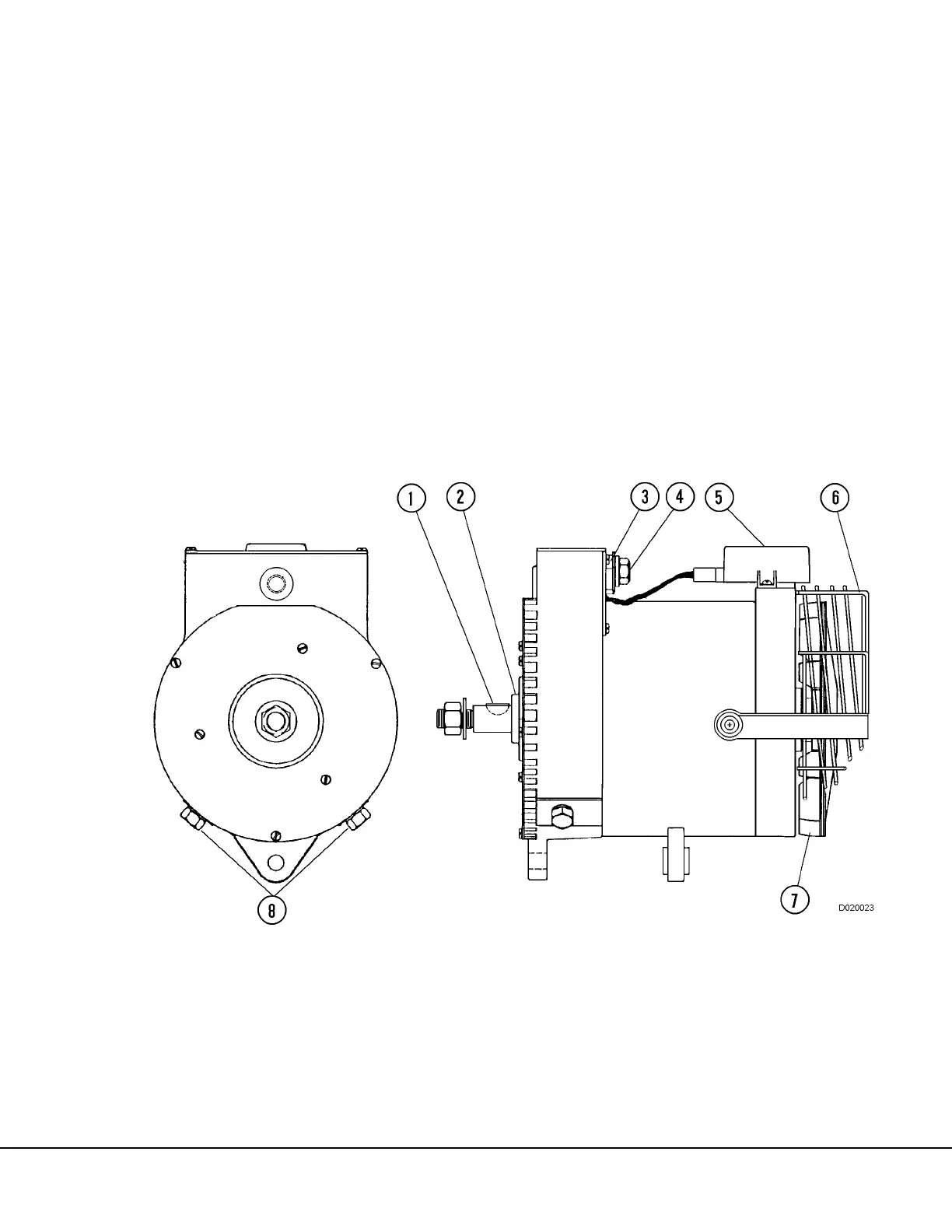
The Niehoff alternator (Figure 2-1) is a heavy duty,
24 VDC unit rated at 240 amps. A solid state voltage
regulator (5) mounted externally on the end housing
assembly provides voltage control during operation.
A single output connection (4) is located on the face
of the control unit (3) for connection to the truck bat-
tery positive circuit. The ground circuit cable can be
attached to either of two terminals (8) located on the
cover plate. A fan guard (6) protects maintenance
personnel from the rotating fan when the engine is
operating.
TROUBLESHOOTING PROCEDURES
(On-Truck)
Most 24 volt charging system problems can be diag-
nosed with the alternator installed on the truck,
operating under normal conditions. Many problems
can be attributed to loose or corroded cable connec-
tors. It is essential that all battery charging circuit
cables are in satisfactory condition and all connec-
tions are clean and securely tightened.
Equipment Required:
• Belt tension scale
• Voltmeter, 0 - 40 volt range
• Ammeter, 0 - 400 amp range