STEERING CIRCUIT OPERATION
The steering/brake pump (2, Figure 4-1) delivers oil
to the high pressure steering filter (7), then to a
bleed down manifold valve (4) which is located on
the inside left frame rail. The bleed down manifold
diverts oil between the steering circuit and brake cir-
cuit. The bleed down manifold directs oil to the
steering accumulators (6), flow amplifier (7), brake
circuit and steering cylinders via the flow amplifier.
Oil entering the accumulator via the bleed down
manifold pushes the floating piston within the accu-
mulator upward, compressing the nitrogen on the
opposite side of the piston. The nitrogen pressure
increases directly with steering circuit pressure. The
top side of the piston is pre-charged to 1400 psi (9
653 kPa) with pure dry nitrogen when the piston is
at the bottom.
The accumulator oil is supplied constantly to the
flow amplifier, via the bleed down manifold. The
accumulators also act as a reservoir for pressurized
hydraulic oil to be used during an emergency situa-
tion should the hydraulic steering oil supply mal-
function for any reason.
If a loss in steering pressure occurs, stop the
truck immediately. The pressure in the accumu-
lator allows the operator to steer the truck only
for a short period. Do not attempt further opera-
tion until the problem is located and corrected.
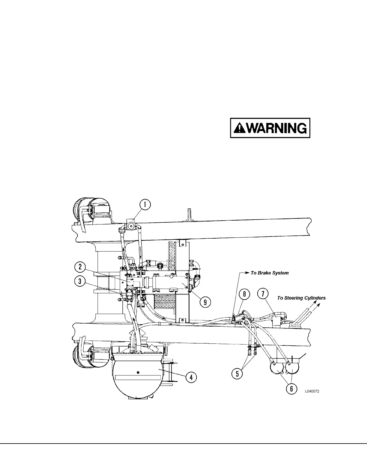
FIGURE 4-1. STEERING CIRCUIT (BOTTOM VIEW)
1. Steering Circuit Filter
2. Steering / Brake Circuit Filter
3. Shut-off Valve
4. Hydraulic Tank
5. Steering Quick Disconnects
6. Steering Accumulators
7. Flow Amplifier Valve
8. Bleeddown Manifold Valve
9. Hoist Circuit Pump