HOIST PUMP
Removal
NOTE: It is not necessary to remove the steering
pump with the hoist pump. The steering pump may
be disengaged and supported as the hoist pump is
removed.
1. Turn the keyswitch “Off” and allow ample time
(approximately 90 seconds) for the accumula-
tors to bleed down. Turn the steering wheel to
be sure no oil remains under pressure.
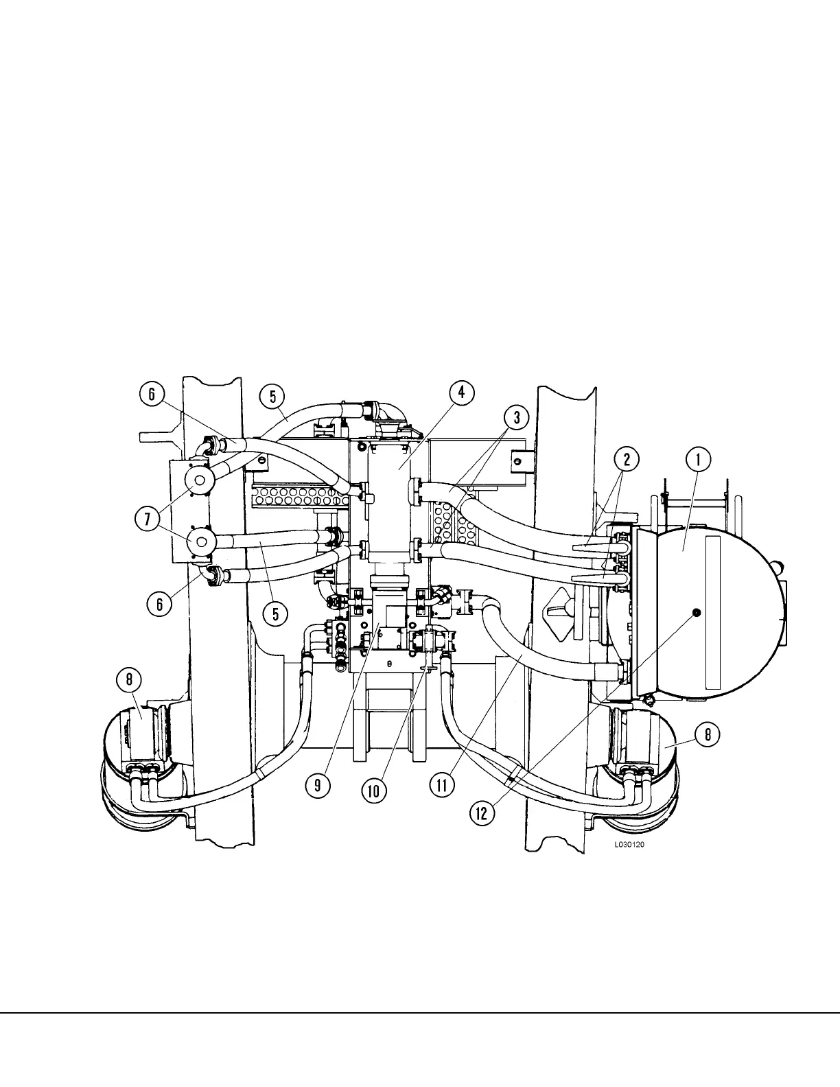
2. Drain the hydraulic tank by use of the drain
valve (12, Figure 3-1) located on the bottom of
the tank.
NOTE: If oil in the hydraulic tank has not been
contaminated, the shut-off valves can be closed and
both pump inlet lines can be drained, eliminating the
need to completely drain the tank. Refer to Figure 3-
1.
3. Remove the rear axle blower hose support
strap.
FIGURE 3-1. HOIST PUMP PIPING (BOTTOM VIEW)
1. Hydraulic Tank
2. Hoist Pump Shut-Off Valves
3. Hoist Pump Suction Hoses
4. Hoist Pump
5. Filter Outlet To Hoist Valve Hose
6. Hoist Pump Outlet To Filter Hose
7. Hoist Circuit Filters
8. Hoist Cylinders
9. Steering / Brake Pump
10. Steering Pump Shutoff Valve
11. Hoist Valve Return To Tank Hose
12. Hydraulic Tank Drain