HOIST PILOT VALVE
Removal
1. Place the hoist control lever in the body down
position. Make sure the body is in the full down
position. Release the hoist control lever to
return the hoist valve spool to the FLOAT posi-
tion.
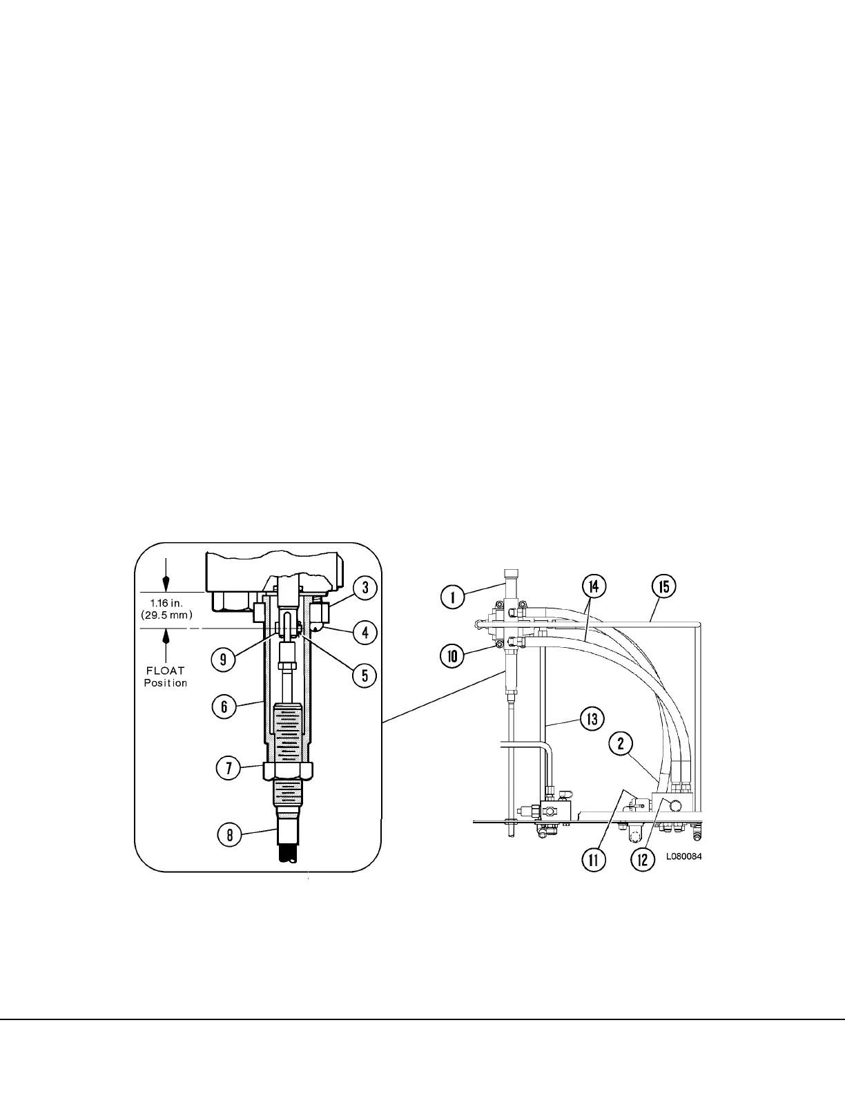
2. Disconnect hydraulic lines at the hoist pilot
valve (1, Figure 8-11). Remove capscrews (4).
3. Loosen and unthread jam nut (7). Unthread
sleeve (6) until cotter pin (5) and pin (9) are
exposed.
4. Remove cotter pin (5) and pin (9).
5. Remove the hoist pilot valve mounting hard-
ware (10). Remove hoist pilot valve. Refer to
hoist pilot valve disassembly for repair instruc-
tions.
Installation
1. Place the hoist pilot valve into position on the
mounting bracket. Secure valve in place with
capscrews (10, Figure 8-11).
2. Position hydraulic lines (2, 13, 14 and 15) over
valve ports and assemble fittings. Tighten
hydraulic line connections securely.
3. Place hoist control lever in spring-centered
position. Adjust pilot valve spool until center-
line of cable attachment hole extends 1.16 in.
(29.5 mm) from the face of the valve body.
4. Align control cable eye with pilot valve spool
hole and insert pin (9). Secure pin in place with
cotter key (5).
5. Thread sleeve (6) upward until contact is made
with valve body. Move flange (3) into position
and secure in place with capscrews (4).
6. Thread jam nut (7) against sleeve (6). Tighten
jam nut securely.
7. Start the engine and check for proper hoist
operation. Observe for leaks.
Disassembly
1. Thoroughly clean the exterior of the valve.
Place the valve in a clean work area for disas-
sembly.
2. Remove machine screw (15, Figure 8-12) seal
plate (16), wiper (13) and O-ring (12).