E03012 2/02 Statex III Electrical Checkout Procedure E3-19
2.2 Digital Input Checks
1. The two digit diagnostic display panel should have a 00 event code to indicate that all previous
event codes have been cleared. If not, press reset switch to clear codes.
2. For the digital inputs listed below, do the PROCEDURE TO ACTIVATE as specified, and verify
that the display status of the digital input name on the MANUAL DIGITAL OUTPUT TEST
SCREEN changes from false (regular display) to = true (inverse display), unless otherwise
noted. Restore any switch settings and wiring changes to their original condition before moving
on to check the next digital input.
3. All digital inputs have now been checked, except contactor feedback inputs, which will be
checked with digital outputs in next section.
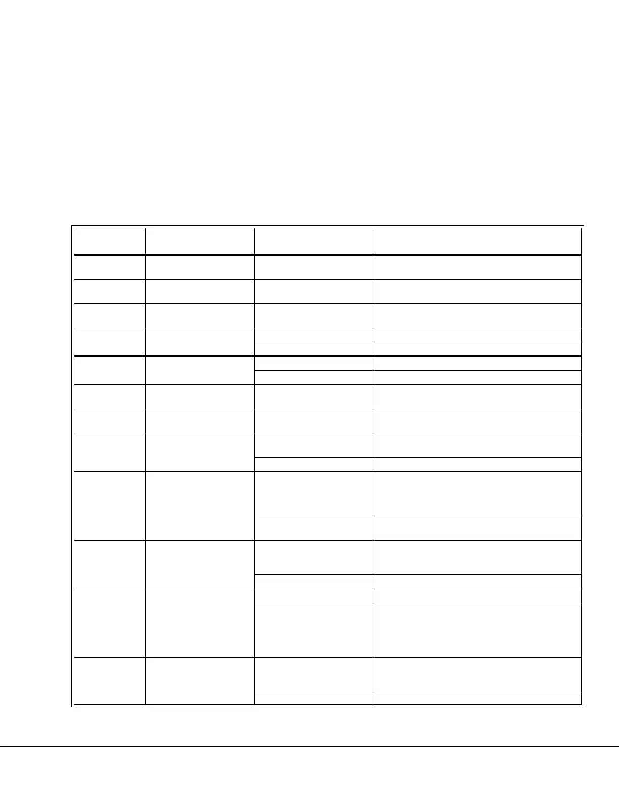
DI NAME DESCRIPTION
PROCEDURE TO
ACTIVATE
FUNCTION
FIRSTSRCH FIRST SEARCH SW
Press Up Arrow Switch on
Two Digit Display.
= true (inverse display) = switch depressed
LASTSRCH LAST SEARCH SW
Press Down Arrow Switch on
Two Digit Display.
= true (inverse display) = switch depressed
2DDRESET LOCAL RESET SW
Press Reset Switch on Two
Digit Display.
= true (inverse display) = switch depressed
AS
ACCELSWITCH
(Non-Fuel Saver Only)
Accelerator pedal applied. = true (inverse display) = ACCEL request =28v input
Pedal released false (regular display) = no ACCEL request =0v input
RS
RETARD SWITCH
(Non-Fuel Saver Only)
Press retard pedal. = true (inverse display) = retard request = 0v input
Pedal released false (regular display) = no request = 28v input
DOS
DUMP OVERRIDE
SWITCH
Press override switch. = true (inverse display) = switch depressed
RSC
RETARD SPEED CON-
TROL SWITCH
Pull retard speed control
switch to On position.
= true (inverse display) = switch depressed
DBUP DUMP BODY UP SWITCH
Remove wire 71F.
= true (inverse display) = body up = 0v input
Verify Body-Up light in cab illuminates.
Restore circuit 71F. false (regular display) = body down = 28v input
2SOS
2 SPEED OVERSPEED
SYSTEM
(LOAD WEIGHT SWITCH)
Disconnect wire 73LS routed
to the rear suspension pres-
sure switches and insulate.
Jumper from 71 to 73LS.
= true (inverse display) = loaded truck = 0v input
Remove 71 to 73LS jumper
(Reconnect 73LS.)
false (regular display) = empty truck = 28v input
IDLESW
IDLE SWITCH
(Non-Fuel Saver only)
Move idle switch from low
(turtle) position to high idle
position.
= true (inverse display) = high idle = 0v input
Place switch in low position. false (regular display) = low idle = 28v input
ACCINH ACCEL INHIBIT SIGNAL
No signal (0v input) = true (inverse display) = inhibit = 0v input
Jumper 73S to 710 to ener-
gize park brake failure relay
coil. (Leave jumper con-
nected to simulate Park
Brake Not Applied)
false (regular display) = not inhibit = 28v input
FAILDIODE
FAILED DIODE PANEL
SIGNAL
Remove wire 73A from FDP
term D.
= true (inverse display) = failed diode = 0v input
Verify that electrical system fault light on instrument
panel comes On with wire 73A removed.
Replace wire 73A. false (regular display) = ok diode = 28v input