L05026 Steering Component Repair L5-1
STEERING CIRCUIT COMPONENT REPAIR
BLEED DOWN MANIFOLD
Removal
NOTE: The Bleed Down Manifold may not have to be
removed from the truck to replace components. If
problem area has been isolated simply remove
defective components and replace with new.
Relieve pressure before disconnecting hydraulic
and other lines. Tighten all connections before
applying pressure.
Hydraulic fluid escaping under pressure can
have sufficient force to enter a person's body by
penetrating the skin and cause serious injury and
possibly death if proper medical treatment by a
physician familiar with this injury is not received
immediately.
1. Turn keyswitch “Off” and allow 90 seconds for
the accumulators to bleed down.
2. Disconnect wires at the bleed down solenoid (1,
Figure 5-1) and steering pressure switch.
3. Disconnect, identify and plug each hydraulic line
to prevent contamination.
4. Remove mounting capscrews and remove the
bleed down manifold (10).
5. Clean exterior of manifold before removing any
components.
Installation
1. Install bleed down manifold. Secure in place
with capscrews. Tighten capscrews to standard
torque.
2. Unplug lines and attach. Tighten connections
securely.
3. Attach electrical leads to the bleed down sole-
noid and steering pressure switch. If check
valves or relief valves were removed, replace
using new O-ring seals.
4. Start the engine and check for proper operation
and leaks. Check steering and brake applica-
tion.
NOTE: Adjustment of the relief valves is not
necessary or recommended. Relief valves are
factory preset. Do not attempt to rebuild or repair if
relief valves are defective. Replace as a unit. The
steering pressure switch and check valves are also
replaced only as units.
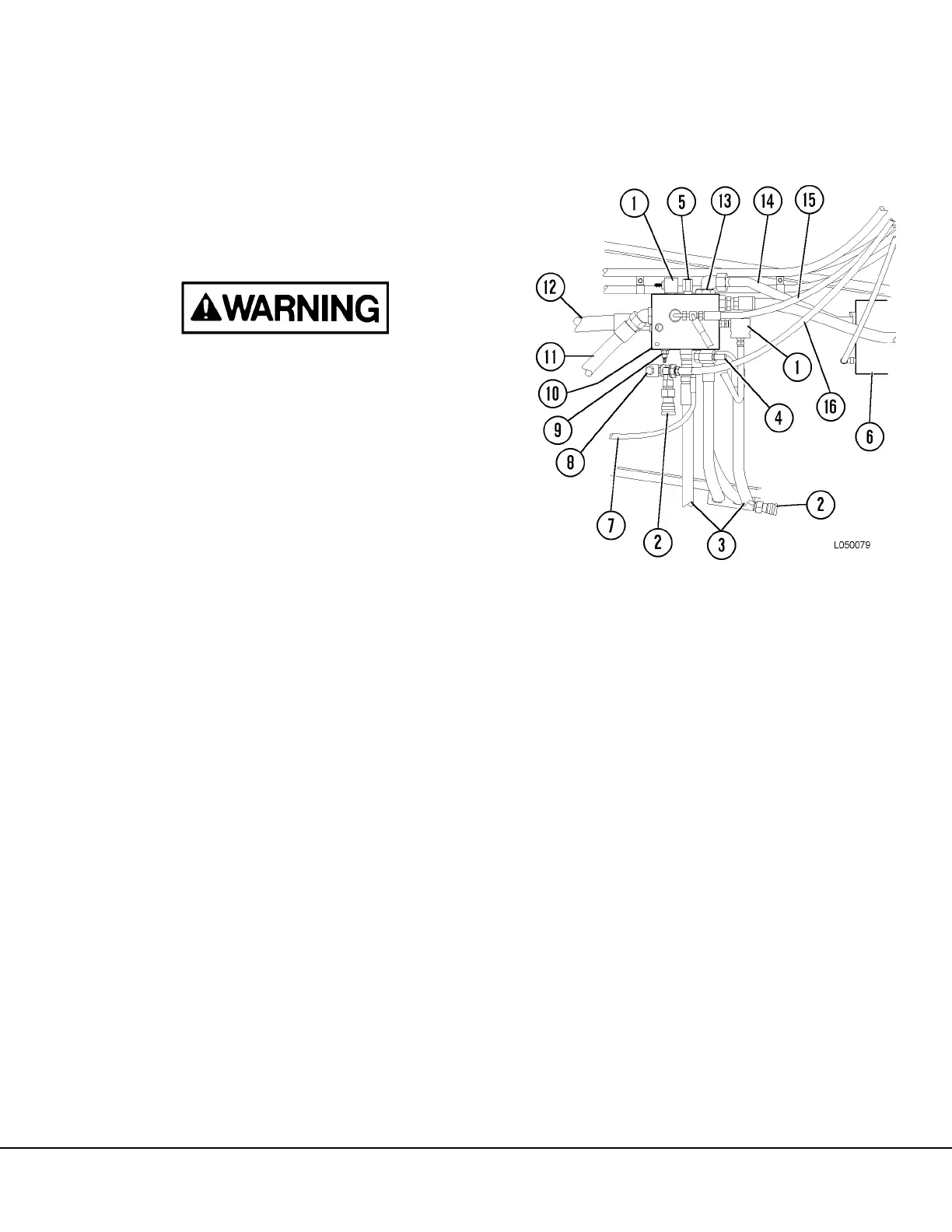
FIGURE 5-1. BLEED DOWN MANIFOLD
1. Bleed Down Solenoid
2. Brake Quick
Disconnect
3. Accumulator Supply
4. Low Steering Pres-
sure Switch
5. Return Relief Valve
(500 psi)
6. Flow Amplifier
7. Unloader Valve Line
8. Check Valve
9. Relief Valve
(4000 psi)
10. Bleed Down Manifold
11. Return Line
12. From Steering Filter
13. Check Valve (Piloted)
14. Outlet To Flow
Amplifier
15. Hoist Pilot Valve
Return Line
16. Supply to Brakes