BRAKE CIRCUIT COMPONENT SERVICE
BRAKE VALVE
The Brake Valve is a pressure modulating valve, actu-
ated mechanically (brake pedal) or hydraulically
through the automatic apply valve (11, Figure 3-1).
The Brake Valve independently controls the pressure
delivered to the front and rear service brake assem-
blies. Apply pressure can be modulated from zero to
maximum braking effort by use of the foot pedal.
Rebuild Criteria
If any one of the following conditions exist, the brake
valve should be removed and repaired:
• Excessive cam rock in pedal actuator.
• Any sign of external leakage.
• Internal leakage at the tank port must be less
than 100 cc/minute with the valve in the released
position and system pressure supplied to the
“P1” and “P2” inlet ports.
• Tank port leakage must be less than 250 cc/min-
ute with valve pilot or manual applied at 3,000 psi
(20 685 kPa) system pressure.
• Failure of the pedal to return to full release posi-
tion.
• Valve holds pressure when in the neutral posi-
tion.
• Varying output pressure with the pedal fully de-
pressed.
Removal
If the Brake Valve is to be removed from the vehicle
for repair or adjustment, additional equipment will be
required as outlined in disassembly, assembly.
NOTE: Minor repairs and service adjustment may not
require the removal of the brake valve.
Before disconnecting pressure lines, replacing
components in the hydraulic circuits, or installing
test gauges, always bleed down hydraulic steering
and brake accumulators. The steering accumula-
tors can be bled down with engine shut down,
turning the key switch “Off” and waiting 90 sec-
onds. Confirm the steering pressure is released by
turning the steering wheel - No front wheel move-
ment should occur. Open bleed down valves (10 &
12, Figure 3-1) located on the brake manifold and
allow both accumulators to bleed down.
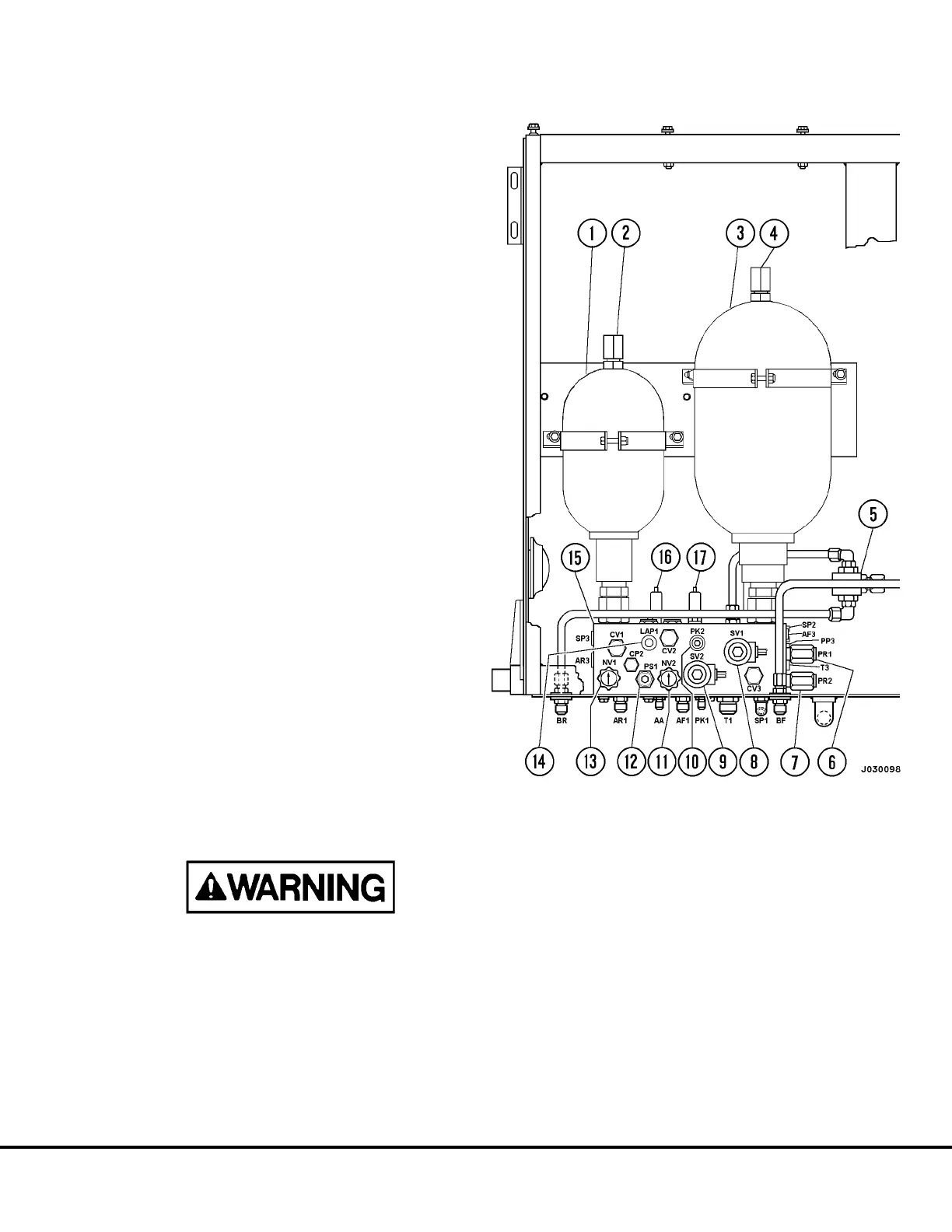
FIGURE 3-1. BRAKE ACCUMULATOR BLEED DOWN
1. Rear Brake Accumulator
2. Charging Valve
3. Front Brake Accumulator
4. Charging Valve
5. Brake Lock Shuttle Valve
6. Brake Lock Pressure Reducing Valve (PR1)
7. Park Brake Reducing Valve (PR2)
8. Brake Lock Solenoid
9. Park Brake Solenoid
10. Park Brake Test Port
11. Bleed Down Valve (Front Brake Accumulator)
12. Automatic Apply Valve
13. Bleed Down Valve (Rear Brake Accumulator)
14. Accumulator Test Port (LAP1)
15.Brake Manifold
16. Low Brake Accumulator Pressure Switch
17. Park Brake Pressure Switch
J03022 1/99 Brake Circuit Component Service J3-1