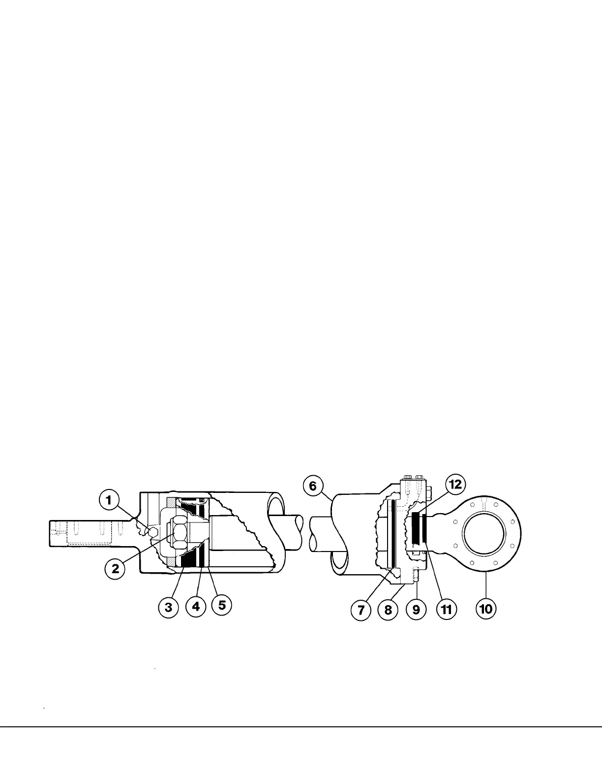
STEERING CYLINDER
For steering cylinder removal and installation
procedure, refer to Section “G”.
Disassembly
1. Remove capscrews (9, Figure 5-20) and pull
gland (8) rod (10) and piston (5) from housing
(6).
2. Remove O-ring & backup ring (7). Remove nut
(2) and remove piston (5). Remove bearing (3)
and piston seal (4).
3. Pull rod (10) from gland (8). Remove rod wiper
(11) and rod seal (12).
Inspection and Cleaning
1. Clean all parts using fresh cleaning solvent, lint
free wiping cloth and dry compressed air.
2. Inspect cylinder housing, gland, piston and rod
for signs of pitting, scoring or excessive wear.
3. Lubricate the cylinder housing, gland, piston
and rod with clean, type C-4 hydraulic oil.
Lubricate new seals, wiper and bearing using
clean, type C-4 hydraulic oil.
Assembly
1. Install new O-ring and backup ring (7, Figure
5-20). The backup ring must be positioned
toward the rod eye.
2. Install new rod seal (12) and rod wiper (11) in
gland (8).
3. Push rod (10) through top of gland, slowly
advancing rod over rod seal and rod wiper.
4. Install new piston seal (4) and bearing (3) on
piston (5). Make sure the piston seal is tight on
piston.
NOTE: Installation of the piston seal may require the
following procedure.
a. Heat the piston seal assembly in boiling
water for 3 to 4 minutes.
b. Remove piston seal assembly from the
water and assemble on the piston. Do not
take longer than 5 seconds to complete
assembly as seal will take a permanent set.
c. Apply even pressure to avoid cocking the
seal.
d. If the seal assembly has taken a slightly
large set, the use of a belt type wrench or
similar tool can be used to compress the
seal to the desired diameter, (tight on pis-
ton).
5. Install piston on rod structure and secure in
place with locknut. Tighten locknut to 2000 ft.
lbs. (2712 N.m) torque.
6. Carefully install rod and gland assembly into
cylinder housing. Insure backup ring and
O-ring on gland are not damaged during instal-
lation.
7. Install capscrews (9) and tighten to 310 ±31 ft.
lbs. (420 ±42 N.m) torque.