N05056 Operator Controls N5-5
OVERHEAD CONTROLS, GAUGES, ETC.
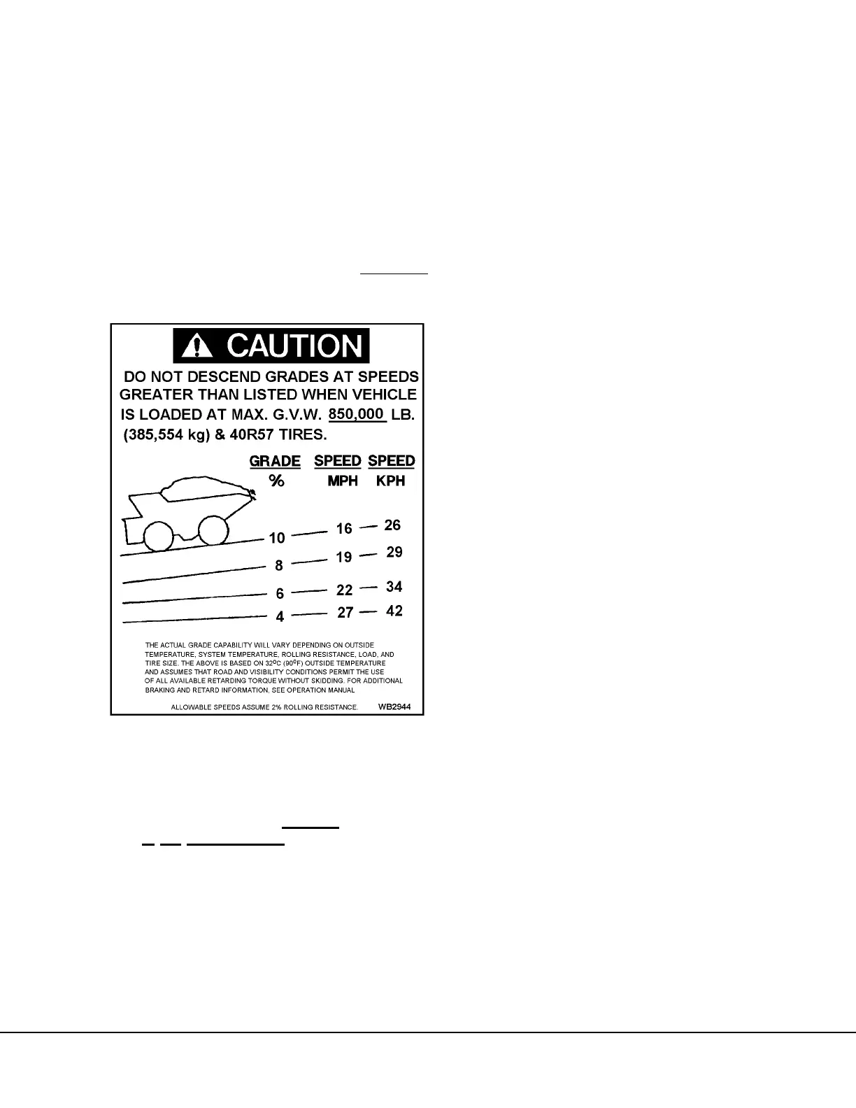
GRADE/SPEED WARNING CHART
The Grade/Speed WARNING chart (8, Figure 5-1
and also shown below) provides the recommended
MAXIMUM truck speeds for descending various
grades with a loaded truck. The operator should ref-
erence this chart before descending any grade with a
loaded truck. Proper use of Dynamic Retarding will
maintain a safe speed.
DO NOT exceed these recommended MAXIMUM
speeds when descending grades with a loaded truck.
The sample chart above applies to a model 830E
equipped with GE787 wheel motors with 31.875:1
gear ratio, 40R57 tires, and 18 element 3-step retard-
ing grids. This decal may change with OPTIONAL
truck equipment such as: wheelmotor gear ratios, re-
tarder grids, tire sizes, etc. ALWAYS
refer to this
decal in
the
operator's cab
, and follow these rec-
ommendations for truck operation.
RADIO SPEAKERS
Radio Speakers (9, Figure 5-1) for the AM/FM Stereo
radio are located at the far left and right of the over-
head panel.
WARNING ALARM BUZZER
This alarm (10, Figure 5-1) will sound when activated
by any one of several truck functions. Refer to ”In-
strument Panel and Indicator Lights”, for a detailed
description of functions and indicators that will acti-
vate this alarm.
CAB RADIO
This panel will normally contain an AM/FM Stereo ra-
dio (11, Figure 5-1). Refer to Section 6, Optional
Equipment, for a more complete description of the ra-
dio and its functions. Individual customers may use
this area for other purposes, such as a two-way com-
munications radio.
WARNING LIGHTS DIMMER CONTROL
This control knob (12, Figure 5-1) permits the opera-
tor to adjust the brightness of the Warning Indicator
Lights.
STATUS / WARNING INDICATOR LIGHT PANEL
This panel (13, Figure 5-1) contains an array of indi-
cator lights to provide the operator with important sta-
tus messages concerning selected truck functions.
Refer to “Instrument Panel and Indicator Lights”, for a
detailed description of these indicators.
WINDSHIELD WIPERS
The windshield wipers (15, Figure 5-1) are powered
by an electric motor. Refer to “Instrument Panel and
Indicator Lights”, for location and description of the
windshield wiper and washer controls.