C4-4 Power Train 4/03 C04026
4. Refer to Figure 4-6. Alternator End-play:
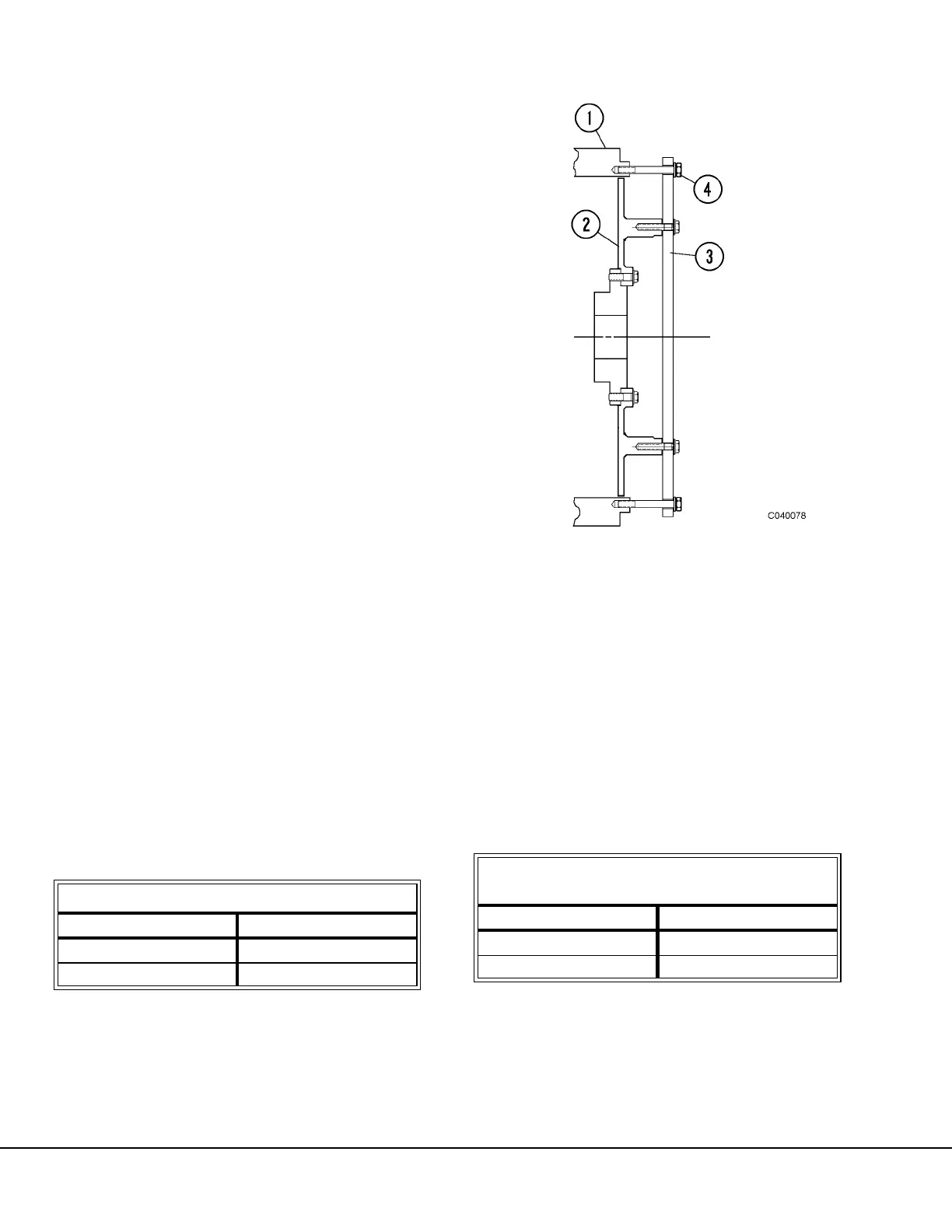
a. Using a flat steel bar (3, Figure 4-6) bolted
rigidly to the alternator rotor (2), install a 5/8"
- 11 capscrew (4) at each end into the alter-
nator housing (1). Leave capscrews finger-
tight.
b. Move the alternator rotor (2) axially towards
the rear (slip-ring end) by alternately tighten-
ing the capscrews (4) one-half-turn-at-a-
time. Do NOT exceed 12.0 ft. lbs. (16.3
N.m) torque on each capscrew. This estab-
lishes the maximum permissible rear travel
for the alternator rotor.
c. Alternately loosen the capscrews (4) one-
turn-at-a-time, until all torque is released.
Carefully remove the bar (3).
Note: The object is to leave the rotor in its
most rearward position.
Refer to Figure 4-5.
d. Carefully measure Dimension “A” (Do not
move alternator rotor) at four locations, 90°
apart, and average the measurements.
1st measurement:_________________________
2nd measurement: ________________________
3rd measurement: ________________________
4th measurement:_________________________
Dimension “A”: ____________________ Average
e. Add 0.010" to Dimension “A”.
f. Record (d + e) as;
“Measurement A”:_________________________
5. Determining Shims: Compare “Measurement C”
(Step 3.c.) with “Measurement A” (Step 4.f.).
a. If C is greater than A, subtract: (C - A) = B
B = _____________ Shim pack thickness
to be installed at location “B”, Figure 4-5.
b. If A is greater than C, subtract: (A - C) = D
D = ___________ Shim pack thickness to
be installed at location “D”, Figure 4-5.
Rotor-to-Drive Ring, Location “B”
Shim Part Number Shim Thickness
TM3467 0.004 in. (0.102 mm)
TM3469 0.007 in. (0.178 mm)
Alternator-to-Flywheel Housing Adapter,
Location “D”
Shim Part Number Shim Thickness
TM3466 0.004 in. (0.102 mm)
TM3468 0.007 in. (0.178 mm)
FIGURE 4-6. ALTERNATOR END-PLAY
1. Alternator Housing
2. Alternator Rotor
3. Steel Bar
4. Capscrew