D02023 24 VDC Electric Supply System D2-19
Solenoid Checks
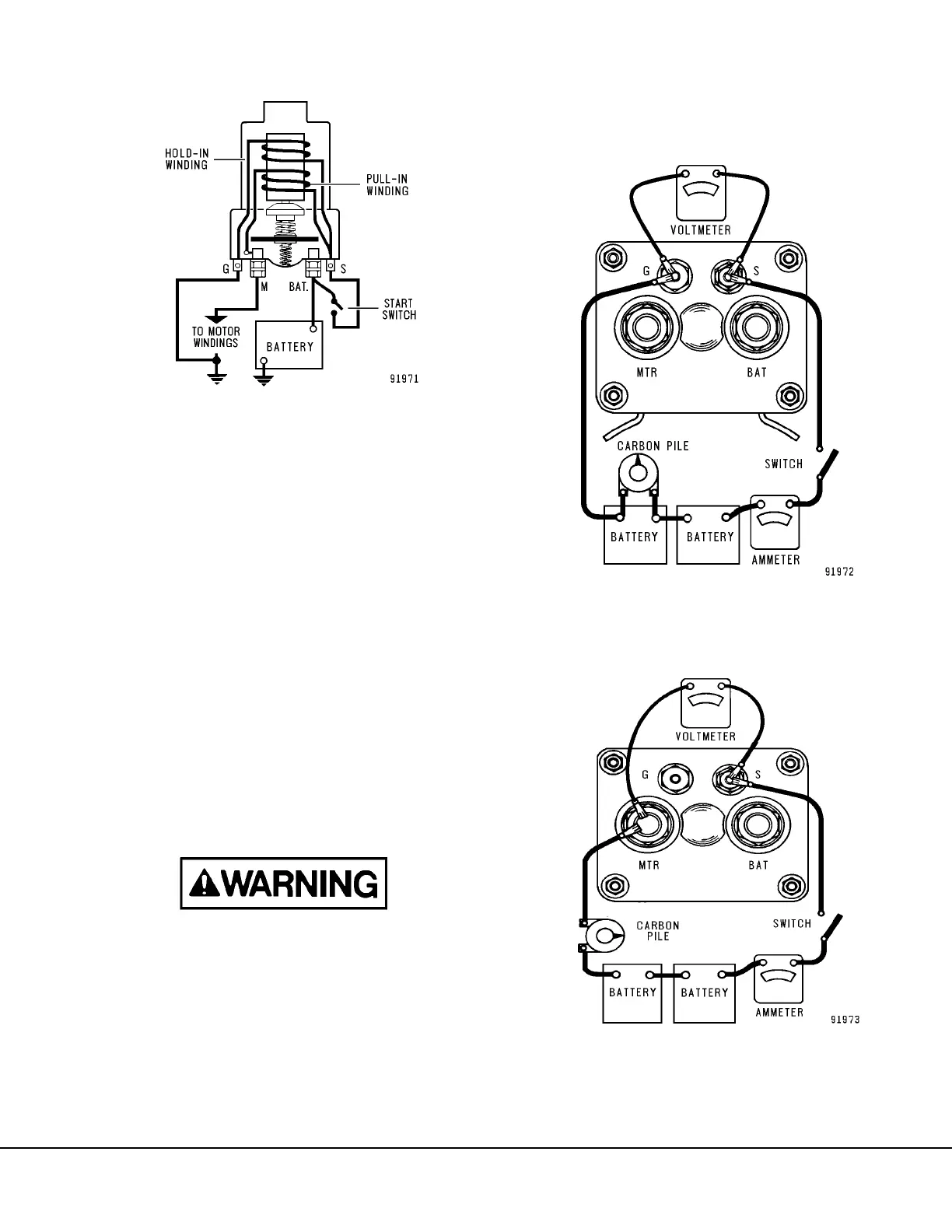
A basic solenoid circuit is shown in Figure 2-9. Sole-
noids can be checked electrically using the following
procedure.
Test
1. With all leads disconnected from the solenoid,
make test connections as shown to the sole-
noid, switch terminal and to the second switch
terminal “G”, to check the hold-in winding (Fig-
ure 2-10).
2. Use the carbon pile to decrease the battery volt-
age to 20 volts. Close the switch and read cur-
rent.
The ammeter should read 6.8 amps
maximum.
3. To check the pull-in winding, connect from the
solenoid switch terminal “S” to the solenoid
motor “M” or “MTR” terminal (Figure 2-11).
To prevent overheating, do not leave the pull-in
winding energized more than 15 seconds. The
current draw will decrease as the winding tem-
perature increases.
4. Use the carbon pile to decrease the battery volt-
age to 5 volts. Close the switch and read cur-
rent.
The ammeter should read 9.0 to 11.5 amps.
NOTE: High readings indicate a shorted winding.
Low readings indicate excessive resistance.
5. To check for grounds, move battery lead from
“G” (Figure 2-10) and from “MTR” (Figure 2-11)
to the solenoid case. Ammeter should read
zero. If not, the winding is grounded.
FIGURE 2-9. SIMPLIFIED SOLENOID CIRCUIT
FIGURE 2-10. SOLENOID HOLD-IN WINDING
TEST
FIGURE 2-11. SOLENOID PULL-IN WINDING
TEST
 Loading...


