D02023 24 VDC Electric Supply System D2-21
Pinion Clearance
To adjust pinion clearance, follow the steps listed
below.
1. Make connections as shown in Figure 2-12.
2. Momentarily flash a jumper lead from terminal
“G” to terminal “MTR”. The drive will now shift
into cranking position and remain so until the
batteries are disconnected.
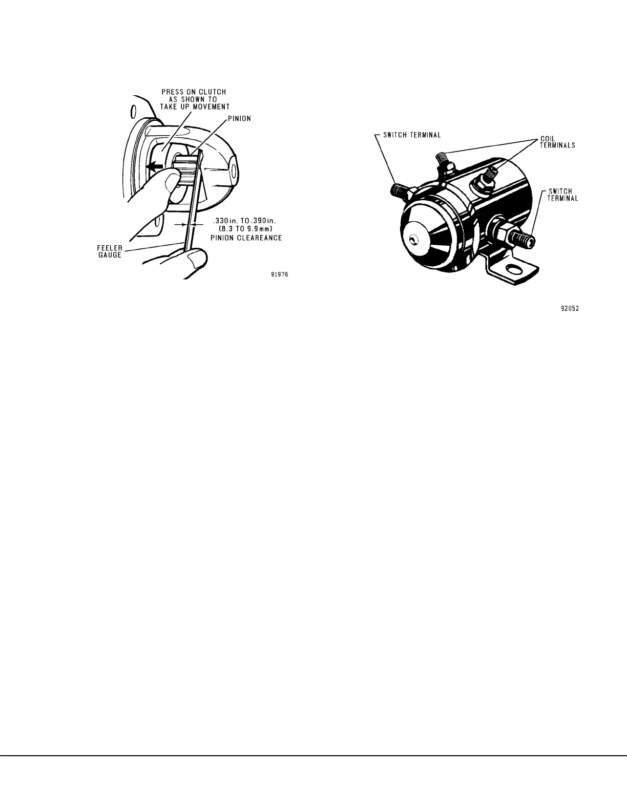
3. Push the pinion or drive back towards the com-
mutator end to eliminate slack movement.
4. The distance between the drive pinion and
housing should be between 0.330 in. to 0.390
in. (8.3 mm to 9.9 mm) as shown in Figure 2-13.
5. Adjust clearance by turning shaft nut (64, Figure
2-8).
MAGNETIC SWITCH
The magnetic switch is a sealed unit and not repair-
able.
Removal
1. Remove battery power as described in Cranking
Motor “Removal”.
2. Disconnect cables from the switch terminals and
wires from coil terminals (Figure 2-14).
NOTE: If the magnetic switch being removed has a
diode across the coil terminals, mark the leads prior
to removal to ensure correct polarity during
installation.
3. Remove mounting capscrews and washers.
Remove switch from mounting bracket.
4. The switch coil circuit can be tested as
described below.
Installation
1. Attach magnetic switch to the mounting bracket
using the capscrews and lockwashers removed
previously.
2. Inspect cables and switch terminals. Clean as
required and install cables.
3. Install the diode across the coil terminals. Be
certain diode polarity is correct. Attach wires
from the truck harness to the coil terminals (See
Figure 2-5).
4. Connect battery power as described in Cranking
Motor “Installation”.
FIGURE 2-13. CHECKING PINION CLEARANCE
FIGURE 2-14. MAGNETIC SWITCH ASSEMBLY
 Loading...


