D3-12 24VDC Electrical System Components D03026
Relay Board 6 . . . . . . . . . . . . . . . Auxiliary Panel
If the Auxiliary Panel, Relay Board 6 is installed,
additional circuits may be added by utilizing the
empty relay terminals provided. (Refer to Figure 3-7.)
To add an additional circuit with a relay, connect the
wires as described below:
The coil circuit for the relay is the “+” and “-” terminal:
“+” terminal is for positive voltage.
“-” terminal is for grounding of the control
circuit.
Either circuit can be switched “open” or “closed” to
control the position of the relay.
The terminals of the switched circuit from the relay
contacts are labeled as follows:
NC - Normally Closed
COM - Common
NO - Normally Open
• “COM” terminal is for the voltage source
(protected by a circuit breaker) coming into the
relay which will supply the electrical power for the
component being controlled.
• “NC” terminal is connected (through the relay) to
the “COM” terminal when the relay is not
energized (when the control circuit terminals “+”
& “-”) are not activated).
• “NO” terminal is connected (through the relay) to
the “COM” terminal when the relay is energized
(by the control circuits “+” & “-”) being energized).
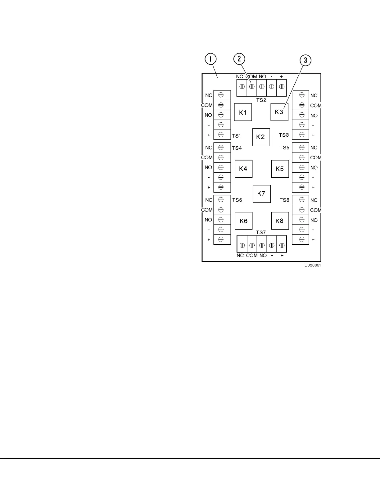
FIGURE 3-7. RELAY BOARD 6
1. Relay Board (RB6)
2. Terminal Strips
(TS1 - TS8)
3. Relays (K1 - K8)