G04015 4/03 Rear Axle Housing Attachment G4-3
PIVOT EYE REPAIR
If damage occurs to the pivot eye (4, Figure 4-3), it
may be necessary to remove it from the rear axle
structure (1) to facilitate repair and bearing replace-
ment.
Removal
To remove the axle housing pivot eye:
1. Follow all the preceeding instructions for "Pivot
Pin Removal".
Be certain axle housing (1) and wheels are
blocked securely!
2. Attach a lifting device to the pivot eye (4).
3. Remove capscrews (2) and flatwashers (3).
Remove pivot eye to work area.
Disassembly
1. Remove spherical bearing (4, Figure 4-2) as
described in "Pivot Eye Bearing, Disassem-
bly".
2. If bearing carrier (3) is damaged or worn, setup
an appropriate tool to press bearing carrier out
of the pivot eye structure bore.
Bearing Carrier (new):
I.D. 8.7484 ± 0.0005 in. (222.209 ± 0.013 mm)
O.D. 9.7520 ± 0.0005 in. (247.701 ± 0.013 mm)
3. Inspect pivot eye structure bore for excessive
wear or damage.
Pivot Eye Bore (new):
9.7500 ± 0.0005 in. (247.650 ± 0.013 mm)
Assembly
1. Setup an appropriate tool to press bearing car-
rier (3, Figure 4-2) into the bore of the pivot eye
structure (1). Be certain the bearing carrier is
pressed fully into the pivot eye bore, flush with
sides. Lube groove in bearing carrier outer
diameter must align with lube fitting hole in
pivot eye structure.
NOTE: With parts to correct size, the fit of the
bearing carrier into the bore of the pivot eye structure
may be: 0.0010 in. - 0.0030 in. (0.025 mm - 0.08 mm)
interference fit.
Freezing the bearing carrier will ease installation.
2. Install spherical bearing (4) as described in
"Pivot Eye Bearing, Assembly".
Installation
1. Be certain mating surfaces of axle housing (1,
Figure 4-3), and pivot eye (4) are clean and not
damaged.
2. Lift pivot eye into position on front of axle hous-
ing. Insert several capscrews (2) and flatwash-
ers (3) to align the parts. Remove the lifting
device.
3. Install the remaining capscrews and flatwash-
ers. Tighten alternately until the pivot eye is
properly seated. Tighten capscrews to 1480 ft.
lbs. (2007 N.m) final torque.
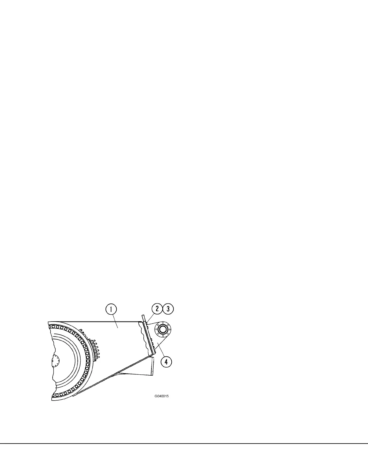
FIGURE 4-3. PIVOT EYE ATTACHMENT
1. Rear Axle Structure
2. Capscrew
3. Flatwasher
4. Pivot Eye