Assembly
1. Replace shell in vise, if removed.
2. Pour a liberal amount of clean C-4 hydraulic oil
into shell to serve as a cushion.
3. With bladder assembly on bench, expel all air to
completely collapse bladder and fold bladder lon-
gitudinally into a compact roll. To maintain rolled
condition of bladder, install gas valve core into the
valve stem, thereby preventing air from entering
the bladder.
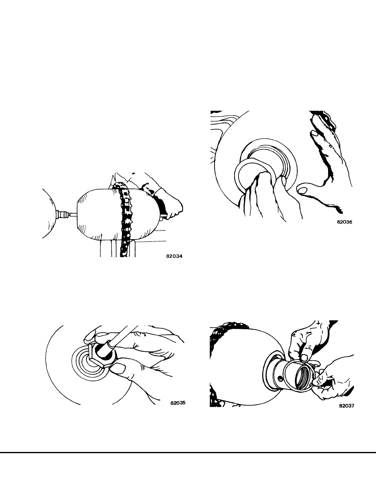
4. Attach bladder pull rod to bladder valve stem.
5. Pass bladder pull rod through shell oil port and out
through valve stem opening. (Refer to Figure
3-19).
6. Pull bladder pull rod out of shell with one hand
while feeding bladder into shell with other hand.
7. Position name plate over valve stem and install
valve stem nut by hand (Figure 3-20). Remove
bladder pull rod.
8. Grasp threaded section of plug and insert poppet
end into shell mouth.
9. Install anti-extrusion ring inside shell. Fold anti-ex-
trusion ring to enable insertion into shell. Place
anti-extrusion ring on plug and poppet assembly
with its steel collar toward shell mouth.
10. Withdraw threaded end of plug through shell
mouth. (Refer to Figure 3-21).
11. Pull plug until seated solidly into position on shell
mouth opening.
12. Install valve core. Using dry nitrogen, slowly pres-
surize bladder with sufficient pressure [approxi-
mately 5 psi (34 kPa)] to hold plug and poppet
assembly in place.
13. Install washer onto plug and poppet assembly and
push until seated against anti-extrusion ring. (Re-
fer to Figure 3-22).
FIGURE 3-19. BLADDER INSTALLATION
FIGURE 3-20. VALVE STEM INSTALLATION
FIGURE 3-21. PLUG ASSEMBLY
FIGURE 3-22. WASHER INSTALLATION
J03022 1/99 Brake Circuit Component Service J3-17