J06020 Rockwell Armature Speed Rear Disc Brakes J6-11
2. Measure spring force at maximum service deflec-
tion on a spring checker. Use the outer spring
guide (8, Figure 6-7) for test setup purposes, as
shown in Figure 6-12.
a. Set up dial indicator spring between checker
arbor and table.
b. Place outer spring guide under checker arbor.
c. Lower arbor firmly onto spring guide and hold
arbor in this position.
d. Set indicator dial to zero (Figure 6-12) and
raise arbor.
e. Place spring over spring guide and lower arbor
slowly until dial indicator again reads zero.
f. Read spring force on checker scale (Figure 6-
12).
3. The value read in Step 2 (f.) is the spring return
force exerted by spring the under maximum
deflection while installed in the piston assembly.
Because of manufacturing tolerances, this can be
as low as 180 lb. (800 N), but will usually mea-
sure greater than 200 lb. (890 N). It is recom-
mended that springs measuring a force of 180
lbs. (800 N) or less under these test conditions be
replaced.
Disassembly of Piston Assembly
To disassemble piston assembly for separate inspec-
tion of return spring (14, Figure 6-7), return pin and grip
assembly (6), proceed as follows:
1. Remove O-ring (2, Figure 6-7) and return pin
washer (3) from return pin.
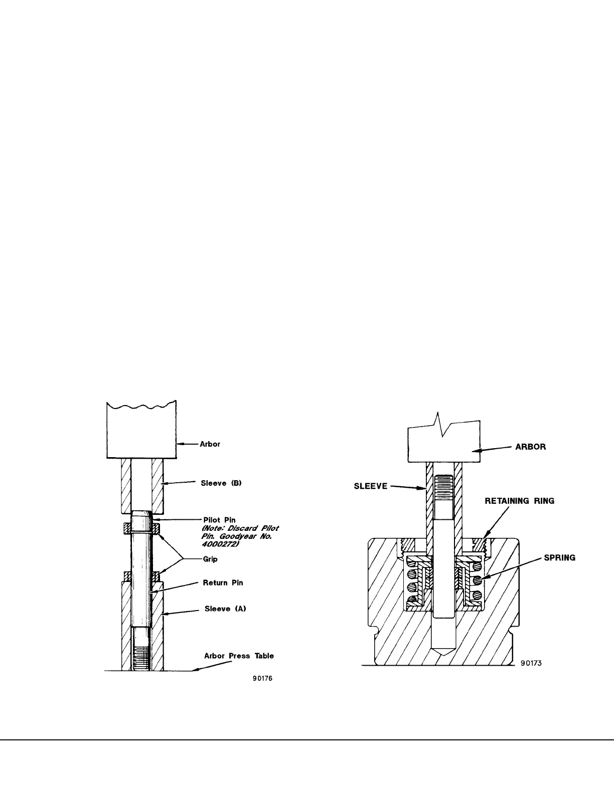
2. Remove lockwire ring (15).
3. Place piston assembly on arbor press table,
place sleeve (A) special tool illustrated in Figure
6-6 or equivalent) over return pin, lower arbor and
fully compress return spring (Figure 6-14) and
hold.
4. Back out threaded retaining ring (4, Figure 6-7).
With compression relieved, threaded ring can
usually be unscrewed by hand. If threads are
burred it may be necessary to use a spanner
wrench. Spanner wrench may also be necessary
for assembly and for setting of built-in clearance.
5. Slowly raise arbor until all compression on the
piston return spring (14) is relieved.
FIGURE 6-13. GRIP INSTALLATION
FIGURE 6-14. RETAINER RING REMOVAL