J06020 Rockwell Armature Speed Rear Disc Brakes J6-17
Rear Brake Conditioning
Note: Front brakes will require burnishing
independently from rear brakes in order to control disc
temperatures.
Extreme safety precautions should be used when
making high-energy/high-speed brake stops on
any downgrade. Safety berms or adequate run off
ramps are necessary for any stopping performance
tests.
1. Temporarily disconnect the FRONT brakes using
the following procedure:
a. Observe safety precautions on the previous
page and relieve stored pressure in hydraulic
system.
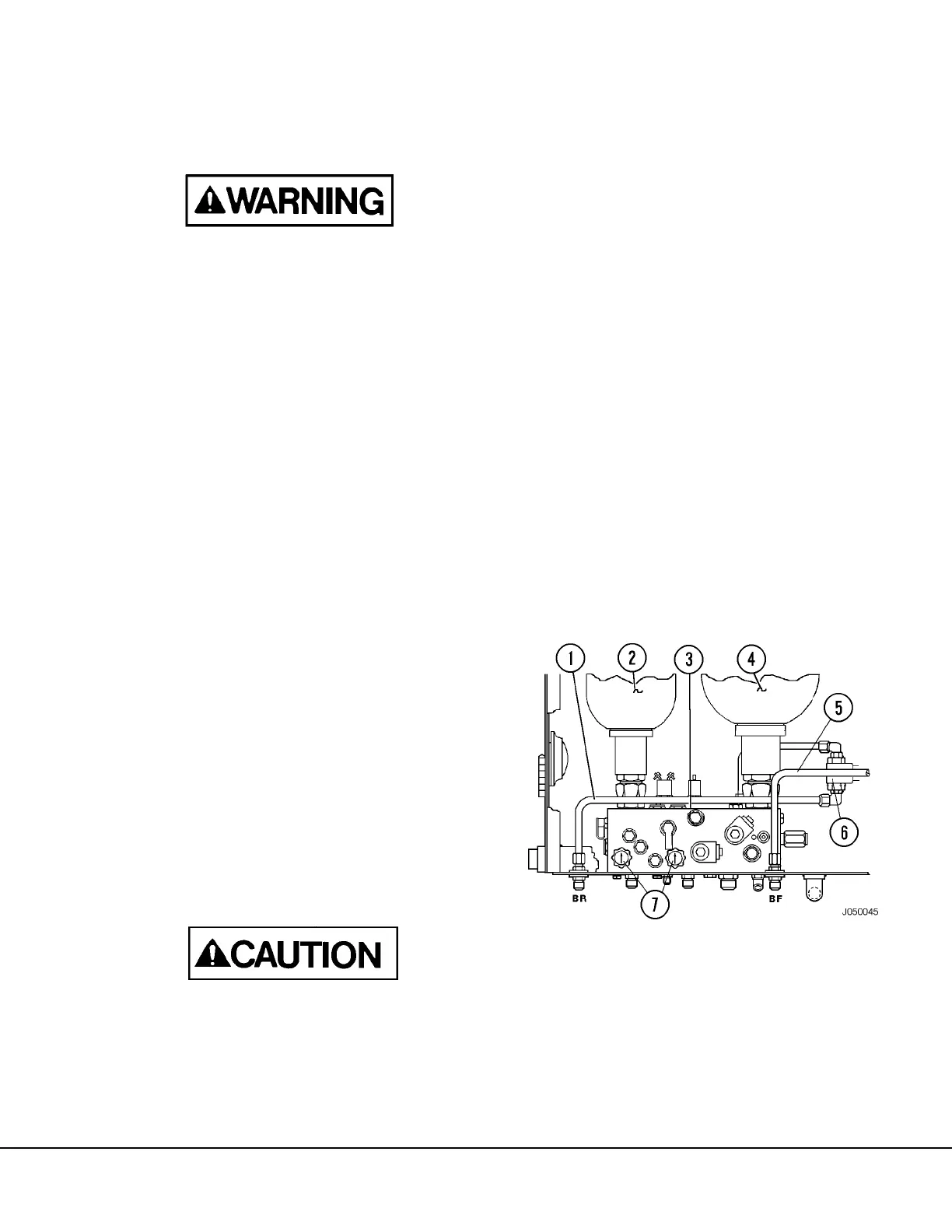
b. Disconnect “BF” hydraulic tube (5, Figure 6-
19) at both ends inside brake control cabinet.
Install a #8, 0.75 x 16UNF-2B, 37° flare Cap
Nut (WA2567, or equivalent) on each fitting
where tube was removed. Tighten caps to
standard torque to prevent leakage. Cap or
plug tube to prevent contamination.
NOTE: This will disconnect the hydraulic sup-
ply from the operator's brake pedal to the front
brakes. There will be a noticeable loss of
“braking action” at the pedal. However, this
method of temporarily disabling the brakes will
still permit the application of Brake Lock, in the
event of an emergency.
c. Close accumulator bleed valves handles (7).
2. Drive empty truck on level terrain at speeds of 5
to 10 MPH while applying (dragging) the brakes
using sufficient pressure to make engine “Work”
until the disc temperatures reach or exceed
600°F (316°C).
NOTE: The Override Switch on the instrument panel
must be depressed and held by the operator in order to
propel the truck with the brakes applied.
Do not exceed 800°F (427°C) disc temperatures
during burnishing.
3. Allow the brake discs to cool to approximately
250°F (121°C) between cycles.
4. Repeat steps 2 and 3.
5. If linings smoke or smell during the second cycle,
continue to repeat burnishing cycle until smoke
and smell are gone or are significantly reduced.
6. Reconnect front brakes:
a. Relieve pressure in hydraulic system accord-
ing to the previous “WARNING” instructions.
b. Remove Cap Nuts and reinstall tube (5).
Tighten tube nuts to standard torque.
c. Close accumulator bleed valve (7) handles.
7. Start engine and check for leaks. Bleed brakes
according to procedure on the following page.
8. Insure all brakes are functioning properly before
releasing truck.
FIGURE 6-19. BRAKE MANIFOLD AND
COMPONENTS
1. “BR” Hydraulic Tube
2. Rear Brake Accum.
3. Brake Manifold
4. Front Brake Accum.
5. “BF” Hydraulic Tube
6. Brake Lock Shuttle
Valve
7. Brake Accumulator
Bleed Valves