L03026 7/02 Hydraulic Component Repair L3-3
Disassembly
NOTE: As parts are removed they should be laid out
in a group in the same order in which they are
removed.
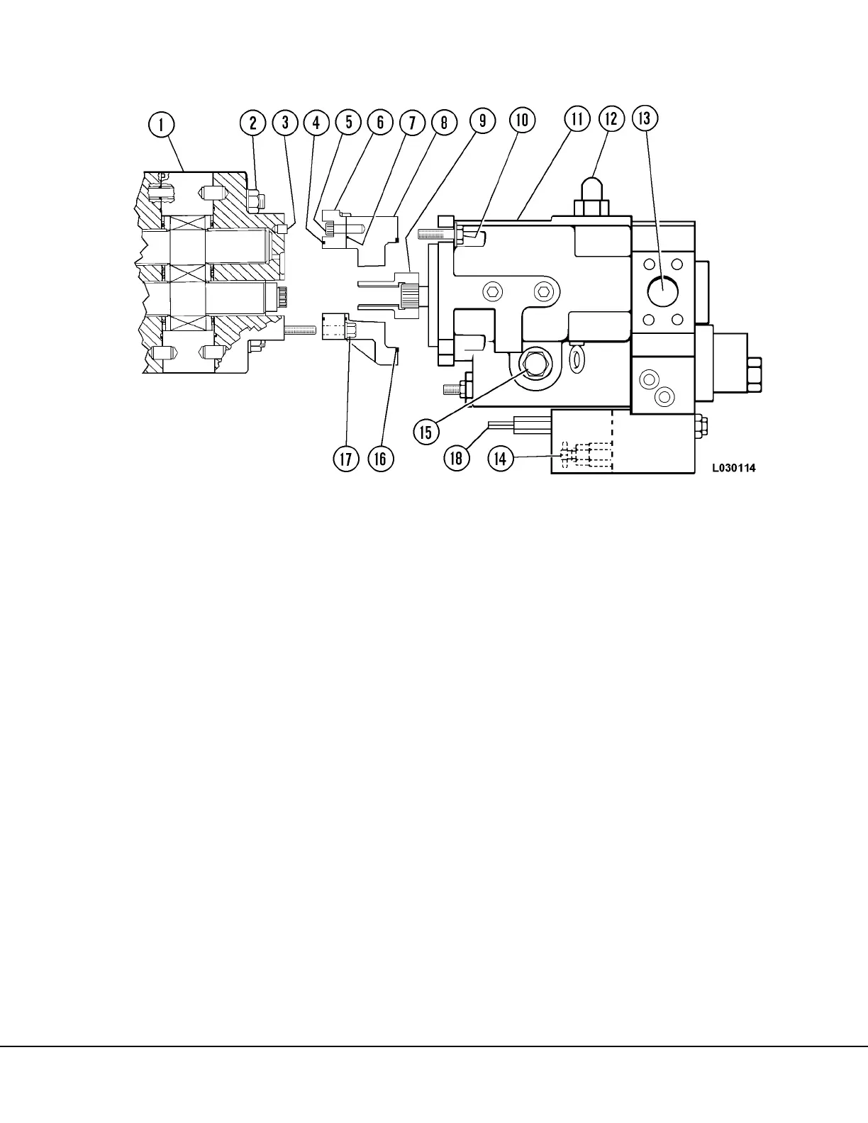
1. Clean the exterior of the pump assembly thor-
oughly. If the steering pump is attached,
remove capscrews (10, Figure 3-2) and pull the
steering pump free of transition plate (8).
Remove O-ring (16).
2. Remove companion flange from driveshaft. If
necessary, heat to 400° to 500°F (204° to
260°C) to ease removal.
3. Remove coupling (9). Remove snap ring (18) if
damaged or replacement of the coupling is nec-
essary. Remove dowels (3) if damaged, or if
replacement of the bearing plate is necessary.
4. The pump may be supported by placing on
wood blocks with the input drive shaft pointing
down. Mark each section nearest the input drive
gear to facilitate reassembly.
5. Remove nuts (17, Figure 3-2) and remove bear-
ing plate (6) with transition plate (8) and O-ring
(4). Remove capscrews (5) securing the bear-
ing plate to the transition plate and remove
O-ring (7). Remove dowels if damaged, or if
replacement of the transition plate is necessary.
6. Remove connector plate (9, Figure 3-3).
Remove O-ring (8) and steel rings (10) and
(14). Remove dowels (6) if damaged, or if con-
nector plate replacement is necessary.
NOTE: If the connector plate is stuck, tap lightly with
a plastic hammer to loosen.
7. Remove backup ring (15), O-ring and retainer
(16) and isolation plate (17). Grasp the drive
gear (12) and idler gear (11) and pull straight up
and out of the gear plate (5) bore. Remove
pressure plate (18) from gears.
8. Remove gear plate (5) and pressure plate (19).
Remove steel rings, backup ring, O-ring and
retainer and isolation plate. Remove O-ring (3)
and stud O-ring (4).
FIGURE 3-2. STEERING PUMP REMOVAL
1. Hoist Pump
2. Nut & Washer
3. Dowel
4. O-Ring
5. Capscrew
6. Bearing Plate
7. O-Ring
8. Transition Plate
9. Coupling
10. Capscrew
11. Steering & Brake Pump
12. Pump Case Drain
13. Inlet Port
14. Compensator Adjuster
15. Plug
16. O-Ring
17. Nut
18. Unloader Adjuster