L5-10 Steering Component Repair L05026
NOTE: If further disassembly is required for the
shock and suction valves refer to Figure 5-8.
NOTE: The flow amplifier valve is equipped with two
shock and suction valves and they are identical. The
shock and suction valves are only serviced as
complete valve assemblies. O-rings 1 & 3, Figure 5-8
are replaceable. Relief valve (20, Figure 5-7) check
valve (54) and counter pressure valve (15) are also
serviced only as assemblies.
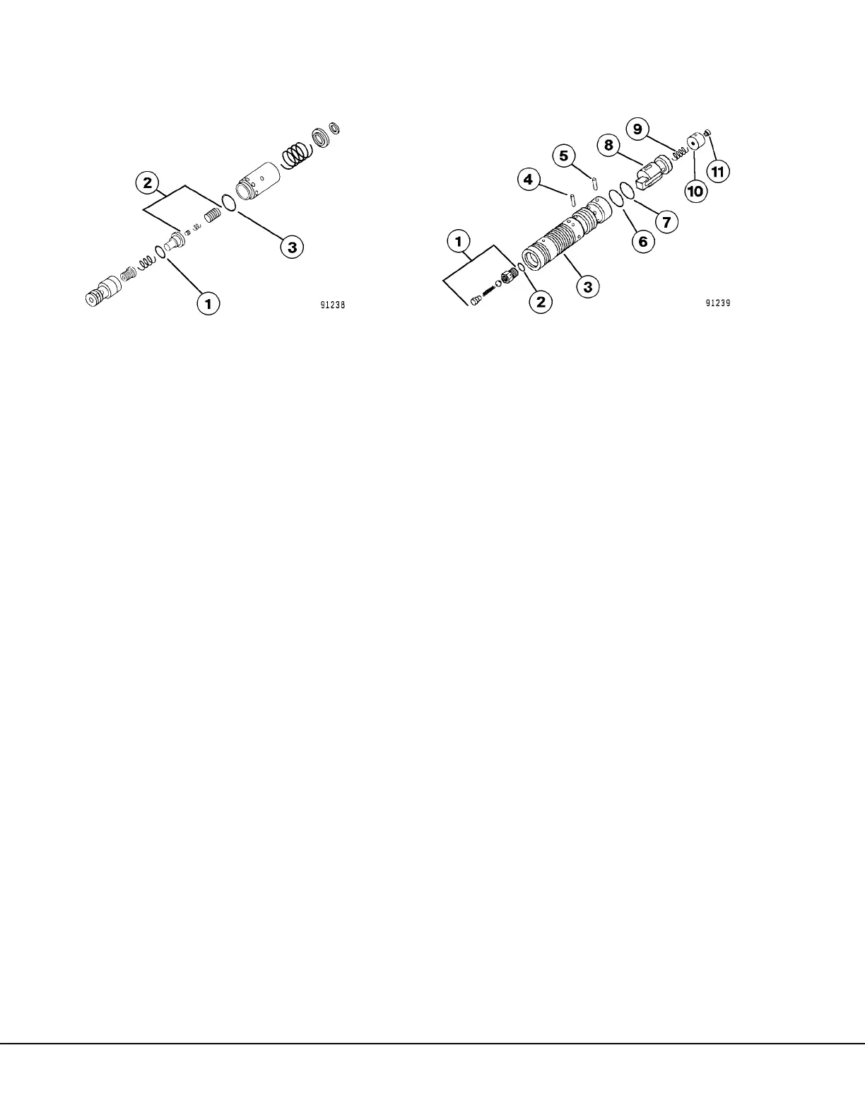
NOTE: Disassembly of the amplifier spool assembly
is only necessary should O-ring (2, Figure 5-9),
spring (9) or orifice screw (11) require replacement,
otherwise replace the amplifier spool assembly as a
complete unit. For complete disassembly refer to
steps 12 & 13.
12. Remove retainer ring (7, Figure 5-9), remove pin
(5). Remove plug (10) and spring (9). Remove
retaining ring (6) and pin (4) and remove inner
spool (8).
13. Unthread check valve (1) and remove. Remove
O-ring (2). Remove orifice screw (11) from plug
(10).
14. Clean and inspect all parts carefully. Make any
replacements necessary.
FIGURE 5-7. SHOCK AND SUCTION VALVE
ASSEMBLY
1. O-Ring
2. Pilot Section
3. O-Ring
FIGURE 5-8. AMPLIFIER SPOOL ASSEMBLY
1. Check Valve
2. O-Ring
3. Spool
4. Pin
5. Pin
6. Retaining Ring
7. Retaining Ring
8. Inner Spool
9. Spring
10. Plug
11. Orifice Screw
 Loading...


