L8-18 Hoist Circuit Component Repair L08031
COUNTERBALANCE MANIFOLD
The counterbalance manifold is located to the rear of
the hoist valve. The internal counterbalance valve
relieves excessive pressure that can develop in the
annulus area of the hoist cylinders if the load sticks to
the tail of the body as the body goes overcenter while
dumping.
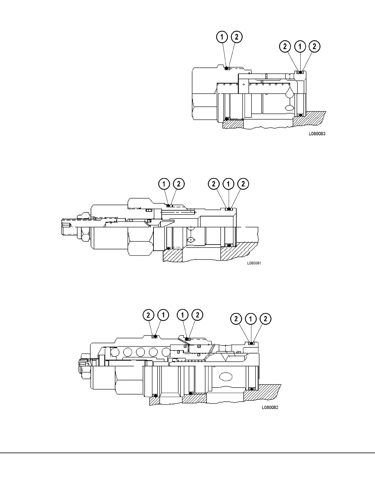
Figures 8-23 through 8-25 show the proper place-
ment of the O-rings and backup-rings on the needle
valve, counterbalance valve and the cavity plug.
For information on how the counterbalance valve
functions, see “Hoist Circuit Operation”, this section.
For adjusting of the counterbalance valve, refer to
the “Hydraulic Checkout Procedure” in this Section.
FIGURE 8-23. NEEDLE VALVE
1. O-Rings 2. Backup-Rings
FIGURE 8-24. COUNTERBALANCE VALVE
1. O-Rings 2. Backup-Rings
F
I
G
U
R
E
8
-
2
5
.
C
A
V
I
T
Y
P
L
U
G
1. O-Rings 2. Backup-Rings