M9-20 Air Conditioning System 05/02 M09010
for HFC 134a Refrigerant
Before a compressor is dismissed as being seized, a
check for proper voltage to the coil should be per-
formed. In addition, the coil should be ohm checked for
proper electrical resistance. The coil should fall within
the following range:
12.0 ± 0.37 Ohms @ 68° F (20° C)
16.1 ± 0.62 Ohms @ 240° F (116° C)
The temperatures specified above are roughly typical
of a summer morning before first start-up and the heat
beside an engine on a hot day. At temperatures in
between those listed above, the correct resistance is
proportionate to the difference in temperature.
Servicing the Compressor Clutch
*Tools are available though your local Kent-Moore dealer.
** These tools are interchangeable.
***For use on multiple groove pulleys.
Use the proper tools to remove and replace clutch
components. Using the recommended tooling
helps prevent damage to compressor components
during maintenance.
Do not drive or pound on the clutch plate, hub
assembly, or shaft. Internal damage to the com-
pressor may result.
1. Remove the belt guard from the front of the air
conditioning compressor.
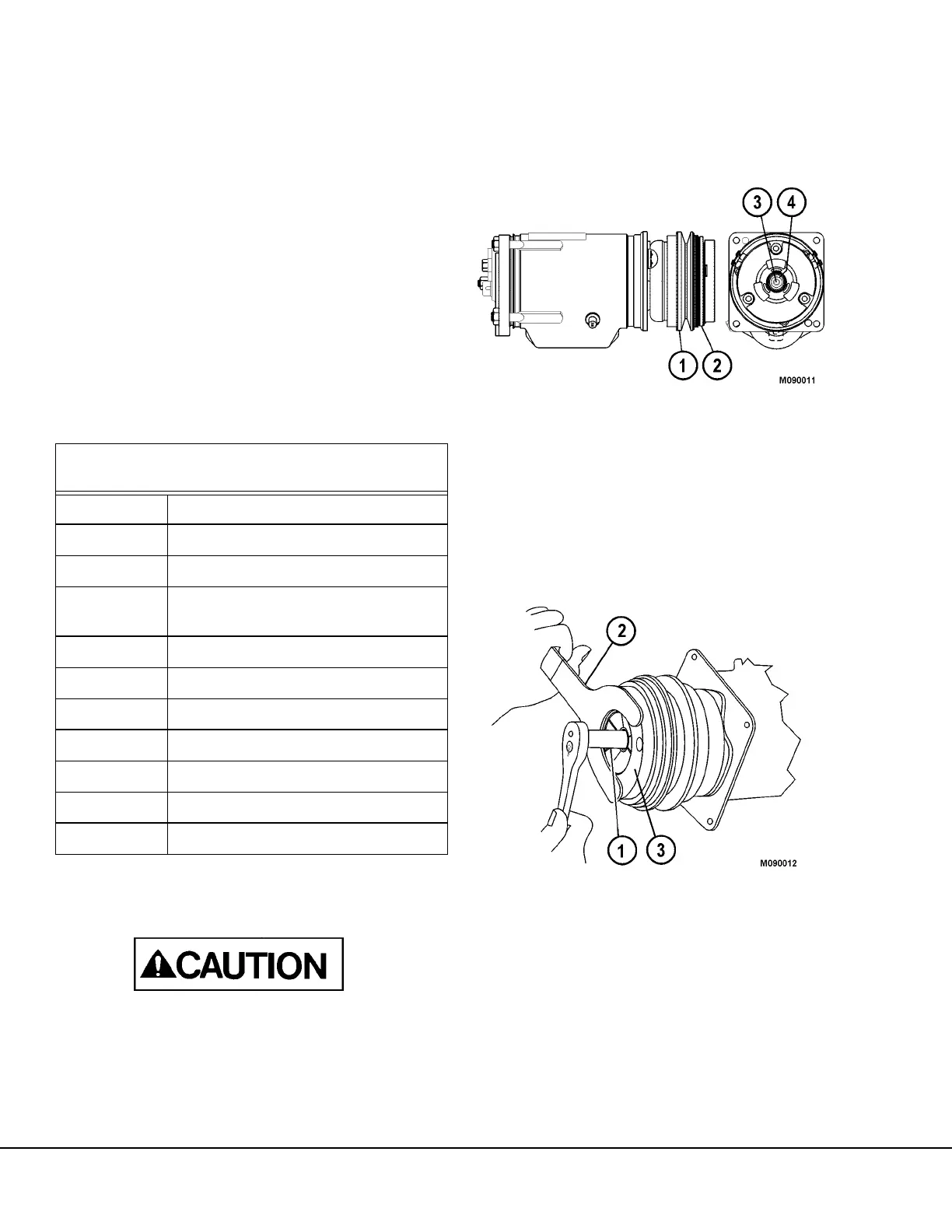
2. Remove the drive belt from compressor belt pulley
(1, Figure 9-10).
* RECOMMENDED TOOLS FOR COMPRESSOR
CLUTCH REMOVAL AND INSTALLATION
J-9399 Thin Wall Socket
**J-9403 Spanner Wrench
**J-25030 Clutch Hub Holding Tool
J-9401
Clutch Plate and Hub Assembly
Remover
J-8433 Pulley Puller
J-9395 Puller Pilot
***J-24092 Puller Legs
J-8092 Universal Handle
J-9481 Pulley and Bearing Installer
J-9480-01 Drive Plate Installer
J-9480-02 Spacer, Drive Plate Installer
FIGURE 9-10.
1. Belt Pulley
2. Clutch Hub/Drive Plate
3. Shaft
4. Locknut
FIGURE 9-11.
1. Thin Wall Socket
2. Clutch Hub Holding Tool
3. Clutch Hub