M9-22 Air Conditioning System 05/02 M09010
for HFC 134a Refrigerant
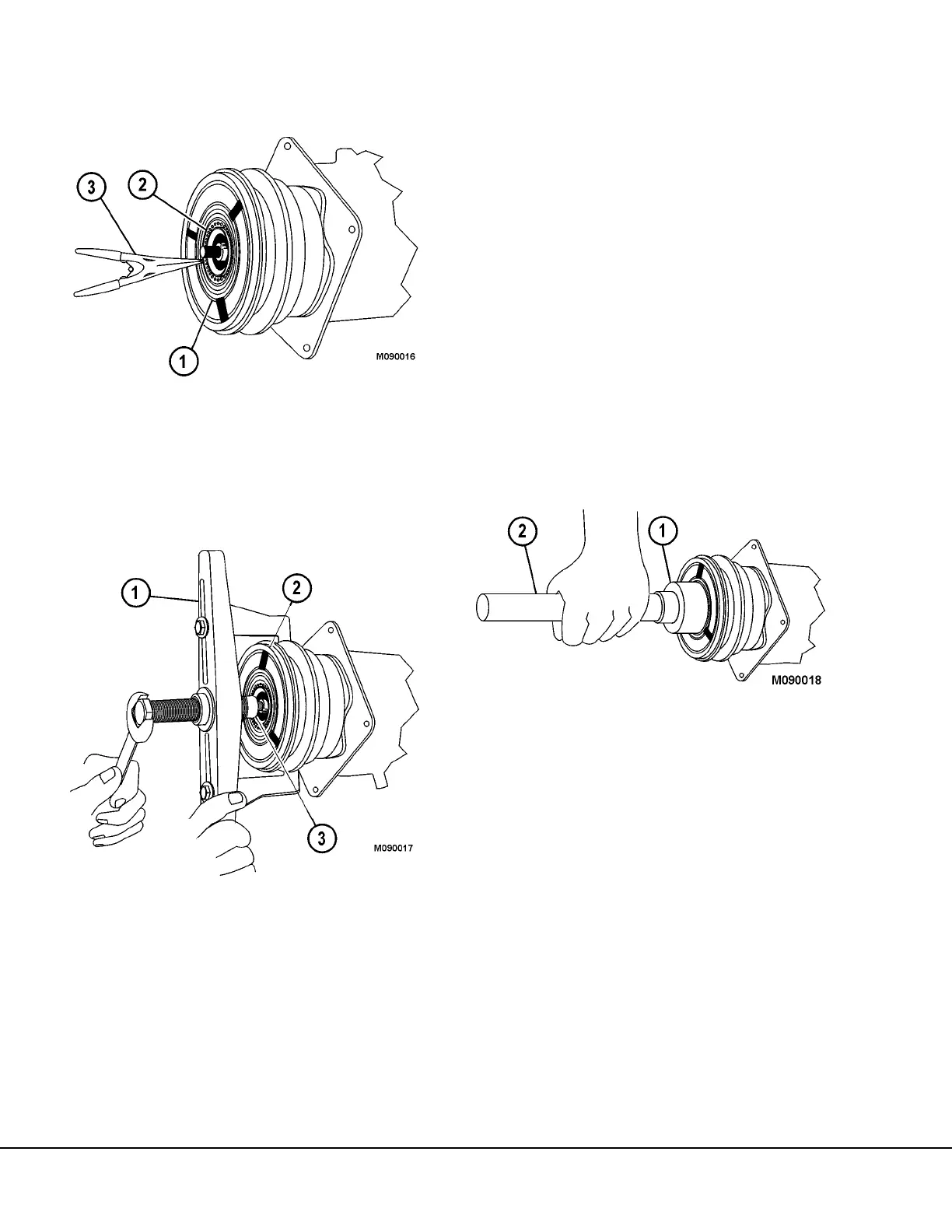
PULLEY REMOVAL
7. Use retaining ring pliers (3, Figure 9-15) to
remove pulley retainer ring (2) from pulley (1).
8. Pry the absorbent sleeve retainer from the neck of
the compressor, and remove the sleeve.
9. Install pulley puller (1, Figure 9-16) and puller pilot
(3) onto the compressor, as shown. If a multiple
groove pulley is used, install puller legs (J-24092)
onto the puller in place of the standard legs.
Extend the puller legs to the back side of the pul-
ley. DO NOT use the belt grooves to pull the pul-
ley from the compressor.
10. Tighten the center screw on the puller against the
shaft of the compressor to remove the pulley.
11. Clean the pulley and pulley bearing with solvent.
Inspect the assembly for damage. Check the
bearing for brinneling, excessive looseness,
noise, and lubricant leakage. Replace the assem-
bly if any of these warning signs are evident.
CLUTCH COIL CHECK
12. Use a multi-meter to ohm check the clutch coil.
The resistance should be as follows:
· @ 68° F (20° C) 12 ± 0.37 ohms
· @ 239° F (115° C) 16.1 ± 0.62 ohms
If the resistance of the coil is not within the specifica-
tions, the clutch will not operate properly. Remove the
retaining ring and replace the coil.
PULLEY INSTALLATION
1. Place the pulley assembly into position on the
compressor. Use bearing installer (1, Figure 9-
17), universal handle (2), and a hammer to lightly
tap the pulley assembly onto the compressor until
it seats. Use of the installer or the equivalent
ensures that the force driving the bearing into
position acts on the inner race of the bearing.
Applying force to the outer race of the bearing will
result in bearing damage.
2. Ensure that the pulley rotates freely. If the pulley
does not rotate freely, remove the pulley and
check for damaged components. Replace any
damaged components and reinstall the pulley.
3. Install the pulley retainer ring and ensure that the
ring is properly seated.
4. Install the absorbent sleeve into the neck of the
compressor. Install the sleeve retainer.
1. Pulley Assembly
2. Pulley Retainer Ring
3. Retaining Ring Pliers
FIGURE 9-15.
FIGURE 9-16.
1. Pulley Puller
2. Pulley Assembly
3. Puller Pilot
FIGURE 9-17.
1. Bearing Installer 2. Universal Handle