M31-6 Reserve Engine Oil System M31001
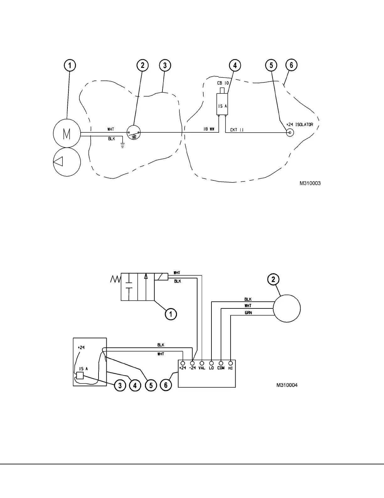
System Electrical Schematics
1. Pumping Unit (Pump 1 & Pump 2)
2. Engine Oil Pressure Switch
3. Engine Subframe
4. 15 Amp Circuit Breaker
5. Power Supply
6. Auxillary Box
FIGURE 31-4. SYSTEM SCHEMATIC
FIGURE 31-5. FILL SYSTEM SCHEMATIC
1. Fill Valve
2. Oil Level Sensor (top of reserve oil tank)
3. 15 Amp Circuit Breaker
4. Battery Disconnect Box
5. Ground Wire
6. Remote Fill Control Box