CP-RIO3-04 Rear I/O CP3002
Page B - 10 ID 1042-9252, Rev. 2.0
P R E L I M I N A R Y
B.5.4 COM Interface
The CP-RIO3-04 rear I/O module provides two identical COM ports for connecting RS-232 de-
vices to the CP-RIO3-04 rear I/O module.
On the 8HP version, the onboard 10-pin COM connectors J2 and J3 are routed to the 9-pin
D-Sub COM connectors J2a and J3a located on the front panel.
On the 4HP version, the COM signals are available only on the onboard 10-pin COM
connectors J2 and J3.
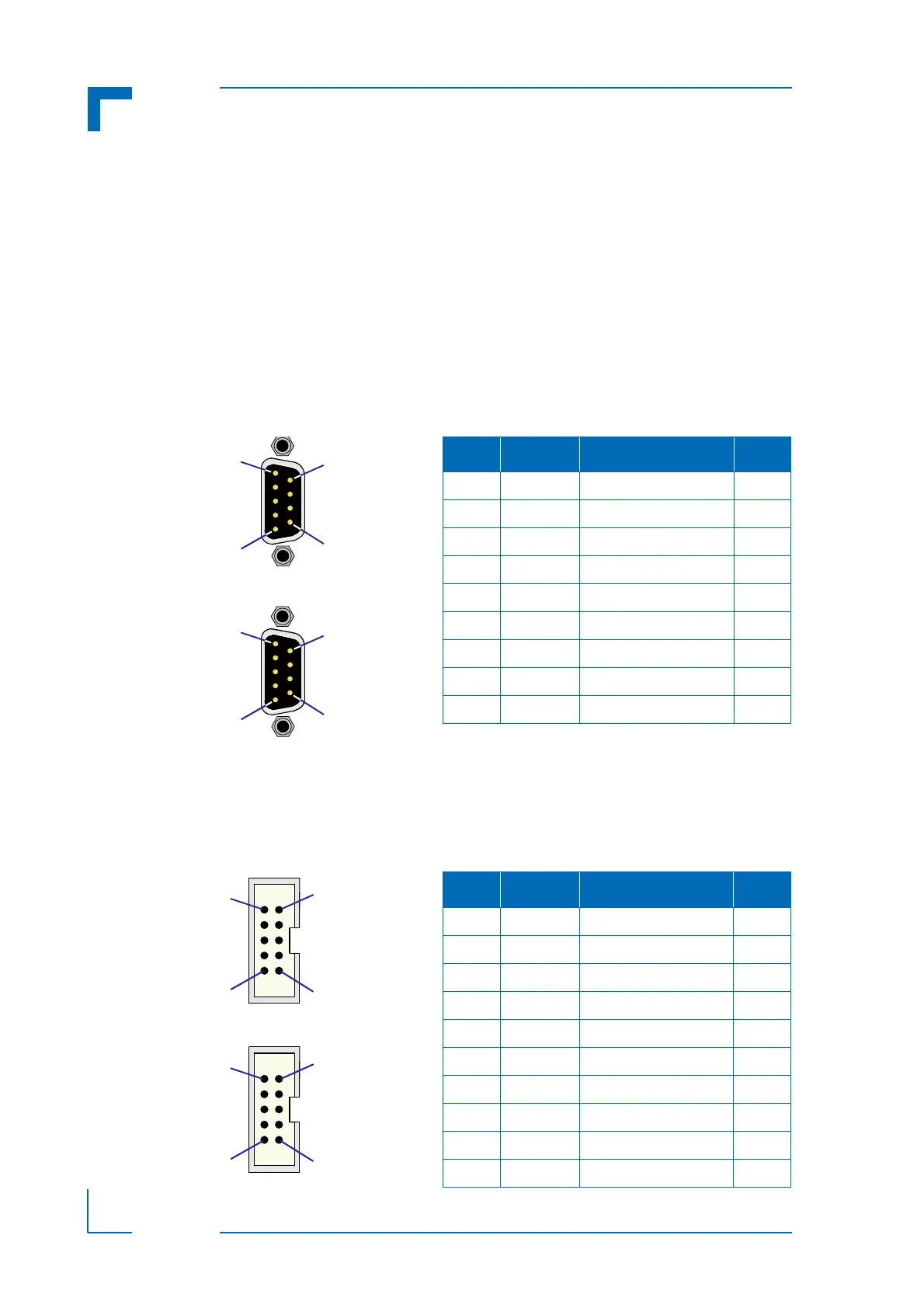
The following figure and table provide pinout information for the 9-pin D-Sub COM connectors
J2a and J3a located on the front panel of the 8HP version.
The following figure and table provide pinout information for the onboard serial port connectors
J2 and J3.
Figure B-7: COM Connectors J2a (COMA)
and J3a (COMB)
Table B-5: COM Connectors J2a (COMA)
and J3a (COMB) Pinout
PIN SIGNAL DESCRIPTION I/O
1 DCD Data carrier detect I
2RXDReceive data I
3 TXD Transmit data O
4 DTR Data terminal ready O
5 GND Signal ground --
6 DSR Data send request I
7 RTS Request to send O
8 CTS Clear to send I
9 RI Ring indicator I
Figure B-8: Serial Port Connectors
J2 (COMA) and J3 (COMB)
Table B-6: Serial Port Con. J2 (COMA)
and J3 (COMB) Pinout
PIN SIGNAL DESCRIPTION I/O
1 DCD Data carrier detect I
2 DSR Data send request I
3 RXD Receive data I
4 RTS Request to send O
5 TXD Transmit data O
6 CTS Clear to send I
7 DTR Data terminal ready O
8 RI Ring indicator I
9 GND Signal ground --
10 NC Not connected --