CP3002 Functional Description
ID 1042-9252, Rev. 2.0 Page 2 - 11
P R E L I M I N A R Y
2.11.3 USB Interfaces
The CP3002 supports six USB 2.0 ports: two on front I/O, two on the high-speed I/O extension
connector J12, two on the rear I/O CompactPCI connector J2. All six ports are high-speed, full-
speed, and low-speed capable.
One USB peripheral may be connected to each port. For connecting more USB devices to the
CP3002 than there are available ports, an external USB hub is required.
2.11.3.1 Front Panel USB Connectors J9 and J10
The CP3002 has two USB 2.0 interfaces that are implemented as two 4-pin, type A USB connec-
tors on the front panel, J9 and J10, with the following pinout:
2.11.4 Integrated Graphics Controller
The processor includes a highly integrated graphics accelerator delivering high performance
3D, 2D graphics capabilities. The integrated graphics controller has two independent display
pipes allowing for support of two independent display screens.
Integrated 2D/3D graphics:
• Intel® Dynamic Video Memory Technology
• Intel® Graphics Performance Modulation Technology
• Intel® Smart 2D Display Technology
• High-performance MPEG-2 decoding
• WMV9/VC1 Hardware acceleration
• Support of DisplayPort interface
• Analog display support for resolution up to 2048 x 1536 pixels @ 75 Hz
• Digital display support for resolution up to 2560 x 1600 pixels @ 60 Hz
Note ...
When connecting peripheral devices to USB2.0 ports, always ensure that
appropriate cables are used.
Note ...
The CP3002 host interfaces can be used with maximum 500 mA continuous
load current as specified in the Universal Serial Bus Specification, Revision
2.0. Short-circuit protection is provided. All the signal lines are EMI-filtered.
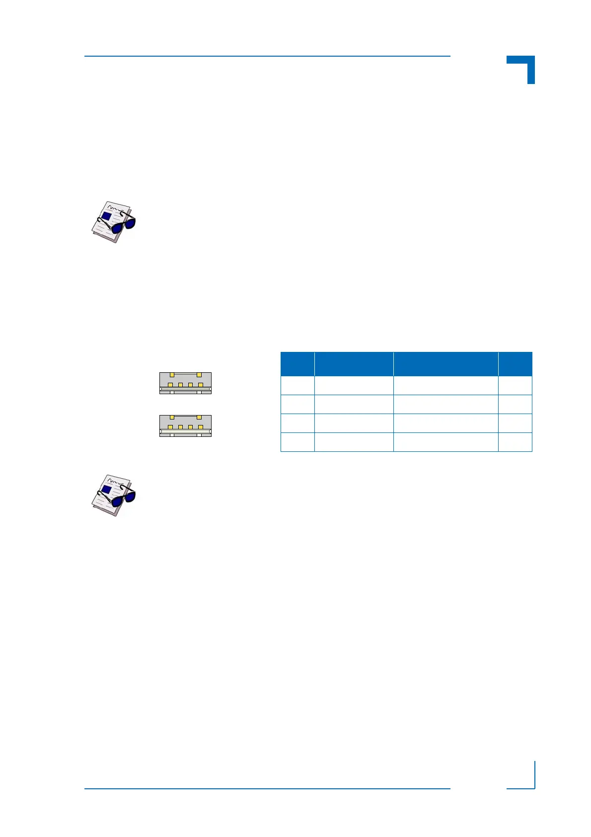
Figure 2-1: USB Connectors
J9 and J10
Table 2-8: USB Connectors J9 and J10 Pinout
PIN SIGNAL FUNCTION I/O
1VCC VCC O
2 USB- Differential USB- I/O
3 USB+ Differential USB+ I/O
4GND GND --