CP3002 Functional Description
ID 1042-9252, Rev. 2.0 Page 2 - 29
P R E L I M I N A R Y
Power Supply and Power Management Signals
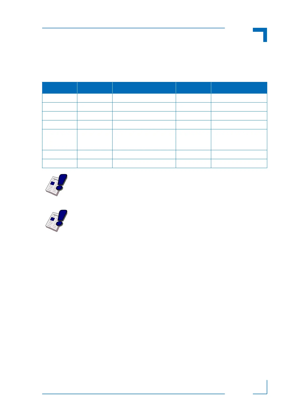
The CP3002 provides the following power supply and power management signals to the rear
I/O module.
For further information regarding the rear I/O signals, please contact Kontron.
Table 2-24: Power Supply and Power Management Signal Description
PIN on J2 SIGNAL FUNCTION DRIVEN BY SIGNALING VOLTAGE
B4 RIO_5V Power supply 5 V CP3002 5 V
E19 RIO_3.3V Power supply 3.3 V CP3002 3.3 V
A4 VI/O Power supply VI/O Backplane 5 V or 3.3 V
A15 PWR_5V_STDBY Power supply 5 V standby Rear I/O module 5 V
C19 PWR_BTN# Power button signal Rear I/O module Open drain (pull-up resistor
on the CP3002) or LVTTL
(3.3 V)
D19 PWR_SLPS3# Sleep S3 signal CP3002 LVTTL (3.3 V)
B15, D7 RSV Reserved -- --
Warning!
Pins B15 and D7 MUST NOT be connected to any signal, either within the
backplane itself or within a rear I/O module.
Failure to comply with the above will result in damage to your board.
Warning!
Pins B4 and E19 are power supply OUTPUTS to supply the rear I/O module
with power. These pins MUST NOT be connected to any other power source,
either within the backplane itself or within a rear I/O module.
Failure to comply with the above will result in damage to your board.