CP3002 Configuration
ID 1042-9252, Rev. 2.0 Page 4 - 3
P R E L I M I N A R Y
4. Configuration
4.1 DIP Switch Configuration
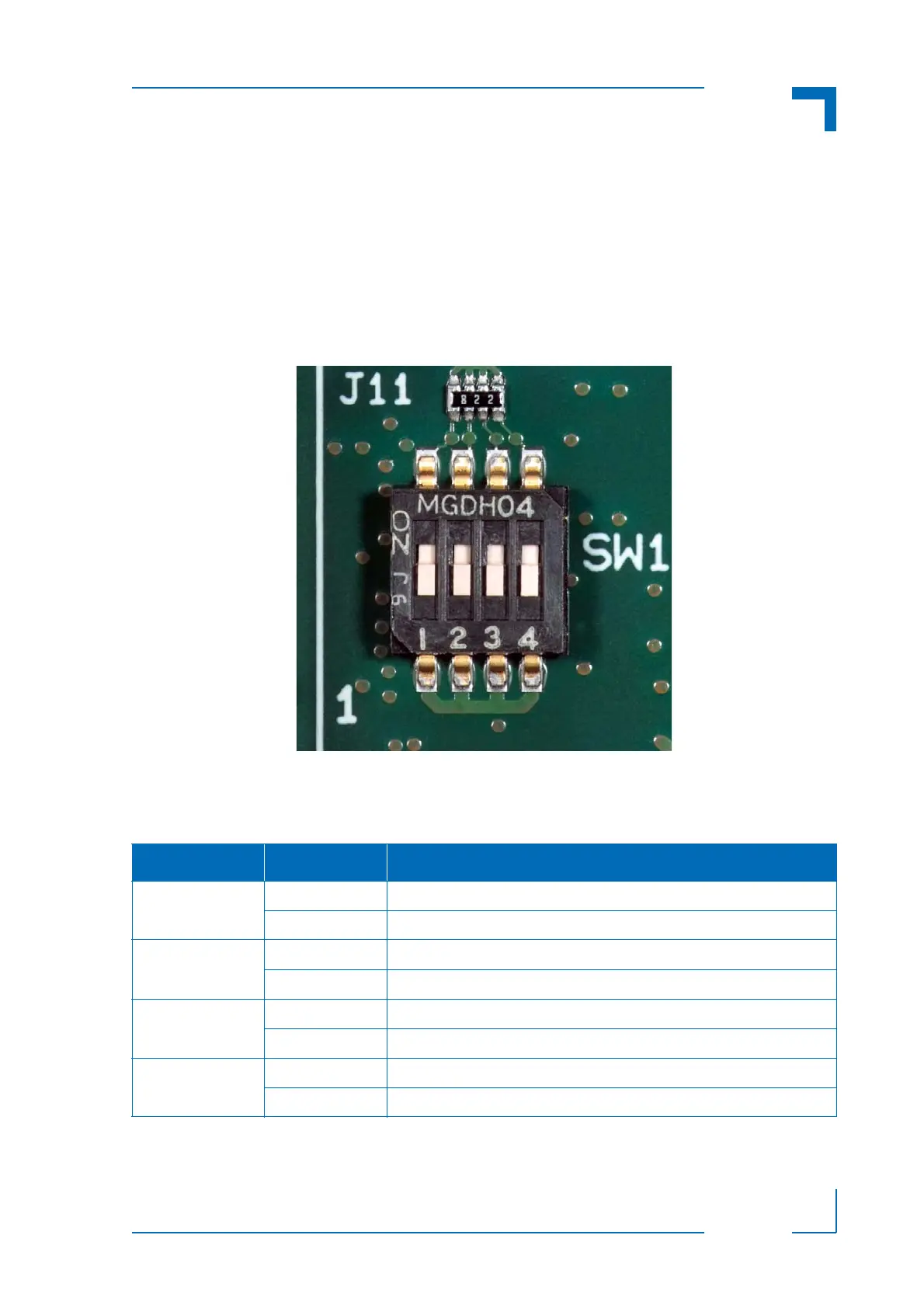
The DIP switch consists of four switches for board configuration: switch 1 for POST code indica-
tion on LED0..3, switch 2 for the SPI boot flash configuration, switch 3 for reset configuration, and
switch 4 for the uEFI BIOS configuration.
Figure 4-1: DIP Switch SW1
The following table indicates the functionality of the four switches integrated in the DIP switch.
The default setting is indicated by using italic bold.
Table 4-1: DIP Switch SW1 Functionality
SWITCH SETTING FUNCTIONALITY
1 OFF Boot-up with POST code indication on LED0..3
ON Boot-up with no POST code indication on LED0..3
2 OFF Boot from the default SPI boot flash
ON Boot from the alternative SPI boot flash
3 OFF Edge-sensitive reset configuration (QM57 reset implementation)
ON Level-sensitive reset configuration (FPGA PGOOD logic to QM57)
4 OFF Boot using the currently saved uEFI BIOS settings
ON Clear the uEFI BIOS settings and use the default values